
Method for determining geological information of underground target body by transient electromagnetic field B

A transient electromagnetic and target technology, applied in the field of geological exploration, can solve problems such as inaccurate apparent resistivity data, difficulty in fine interpretation of electromagnetic sounding, and inability to objectively reflect the electrical characteristics of geoelectric sections, so as to eliminate multiple solutions Effect

Active Publication Date: 2015-02-18
INST OF GEOLOGY & GEOPHYSICS CHINESE ACAD OF SCI
View PDF8 Cites 14 Cited by
  • Summary
  • Abstract
  • Description
  • Claims
  • Application Information

AI Technical Summary

Problems solved by technology

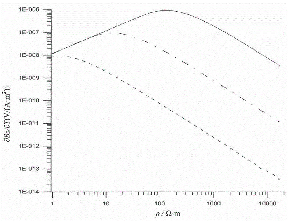
This distorts the curve of apparent resistivity changing with time and transmitting and receiving distance. In addition, the relationship between V(t) / I or dB / dt and resistivity is not one-to-one correspondence, such as image 3 As shown, this results in inaccurate apparent resistivity data, which cannot objectively reflect the electrical characteristics of the geoelectric section, and causes certain difficulties in the fine interpretation of electromagnetic sounding data.

Method used


Image

  • Method for determining geological information of underground target body by transient electromagnetic field B
  • Method for determining geological information of underground target body by transient electromagnetic field B
  • Method for determining geological information of underground target body by transient electromagnetic field B

Examples


Embodiment Construction

[0041] The present invention is described in detail below with reference to accompanying drawing and embodiment:

[0042] image 3 The middle solid line represents the change curve of dB / dt response with resistivity at t=0.001s, the dotted line represents the change curve of dB / dt response with resistivity at t=0.01s, and the dotted line represents the change curve of dB / dt response with resistivity at t=0.1s. Resistivity change curve. It can be seen from the figure that there is no one-to-one correspondence between the dB / dt response and the resistivity change at the short 0.001s moment or the large 0.1s moment. This makes the use of dB / dt to define the apparent resistivity has a dual value problem.

[0043] Figure 4 The solid line in the middle represents the curve of B-field response versus resistivity at t=0.001s, the dotted line represents the curve of B-field response versus resistivity at t=0.01s, and the dotted line represents the curve of B-field response versus r...


PUM


Abstract

The invention relates to a method for determining the geological information of an underground target body by a transient electromagnetic field B. The method comprises the steps of: by using an earth lead, transmitting a primary field into the ground for the underground target to be detected; after the primary field is closed, by applying an induction coil, measuring the induced electromotive force V which is generated in a horizontal coil by the change of a secondary magnetic field along the vertical direction; converting the induced electromotive force V into a magnetic field differential parameter dB / dt; converting the parameter dB / dt into a parameter of the field B by integration; determining the apparent resistivity of the target body according to the parameter of the field B; determining the geological information of the underground target according to the apparent resistivity of the target body. During data interpretation, whole-process apparent resistivity extraction is carried out on the data of the field B by dichotomy, so that the accurate exploration for the geological target body is completed. Compared with the conventional method for calculating the apparent resistivity by the induced electromotive force V, the method provided by the invention is capable of eliminating the multiplicity of solution of the apparent resistivity, and is more beneficial to the exploration of a deep good-conduction target body; furthermore, after the method is used, the detailed geological information of the geological target body can be obtained.

Description

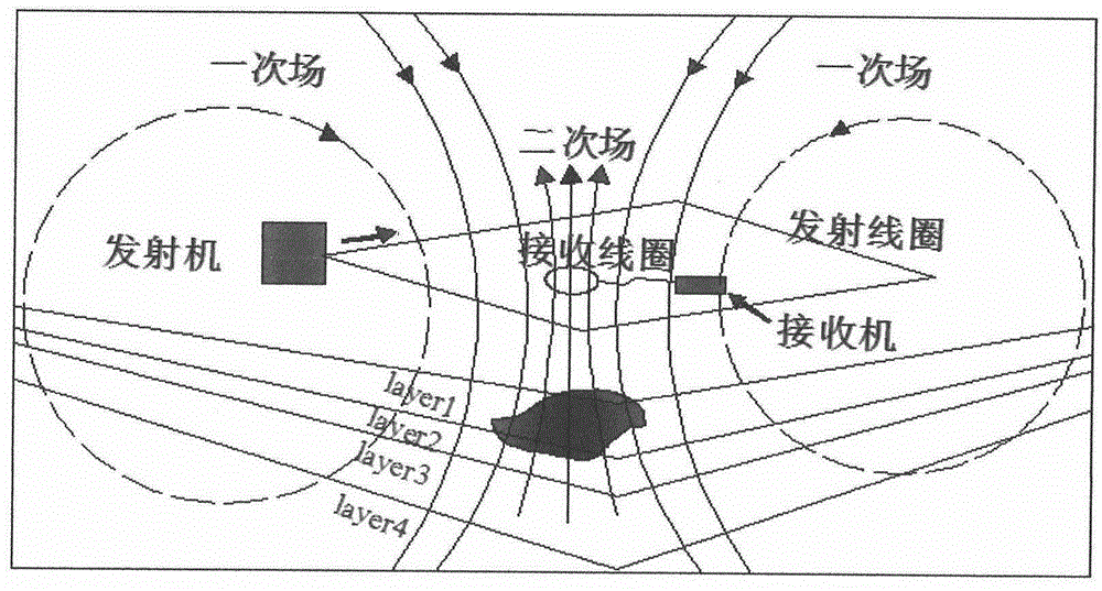
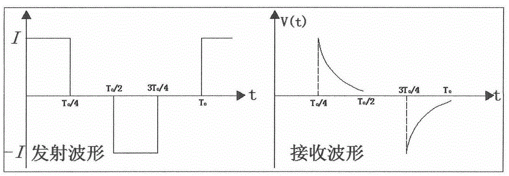
technical field [0001] The invention relates to a geological exploration method, in particular to a method for determining geological information of an underground target body by a transient electromagnetic B field. Background technique [0002] Transient Electromagnetic Method (TEM) is a time-domain artificial source electromagnetic detection method based on the principle of electromagnetic induction. It uses step wave electromagnetic pulse excitation, uses ungrounded return line or grounding wire to emit a primary field underground, and measures the induced secondary field produced by the underground medium over time after the primary field is powered off to achieve the search. A geophysical prospecting method for various geological targets. It works as figure 1 shown. Its transmit waveform and receive waveform are as follows figure 2 shown. [0003] In the existing geophysical exploration, the relatively simple definition formula of apparent resistivity is often int...

Claims


Application Information

Patent Timeline
IPC IPC(8): G01V3/10
Inventor 薛国强崔江伟李貅
Owner INST OF GEOLOGY & GEOPHYSICS CHINESE ACAD OF SCI
Learn More