
Rotary kiln for cement production

A rotary kiln and cement technology, applied in rotary drum furnaces, furnaces, lighting and heating equipment, etc., can solve the problems of welding seam opening, increased use and maintenance costs, thermal expansion and contraction of components, etc., to avoid the fracture of the connection position , The effect of reducing the use and maintenance costs and reducing the maintenance workload

Active Publication Date: 2015-02-18
ZHANGQIU HUAMING CEMENT
View PDF6 Cites 2 Cited by
  • Summary
  • Abstract
  • Description
  • Claims
  • Application Information

AI Technical Summary

Problems solved by technology

[0002] The cold air jacket of the rotary kiln used for cement production in the prior art includes two semicircular arc structures, which are assembled and connected into a cylindrical shape, and then directly welded on the kiln shell with steel plates as connecting ribs , the problem of this welding structure is that due to the high temperature environment, after the equipment has been used for a period of time, due to the temperature changes when the rotary kiln is running or shutting down, the parts frequently expand with heat and contract with cold, resulting in weld opening or connecting ribs Fracture, and every time the welding fracture phenomenon occurs at the weakest position, which affects the normal operation of the equipment system, and in severe cases, the parts are displaced and forced to stop
Because the equipment is relatively heavy, it also increases the cost of use and maintenance, and increases the labor intensity of maintenance personnel

Method used


Image

  • Rotary kiln for cement production
  • Rotary kiln for cement production

Examples


Embodiment Construction

[0016] In order to better understand the present invention, the embodiments of the present invention will be explained in detail below with reference to the accompanying drawings.

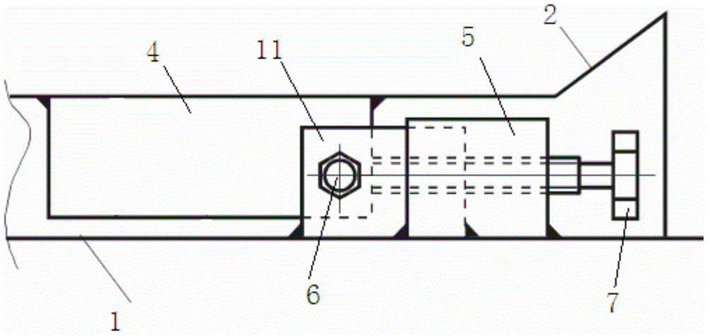
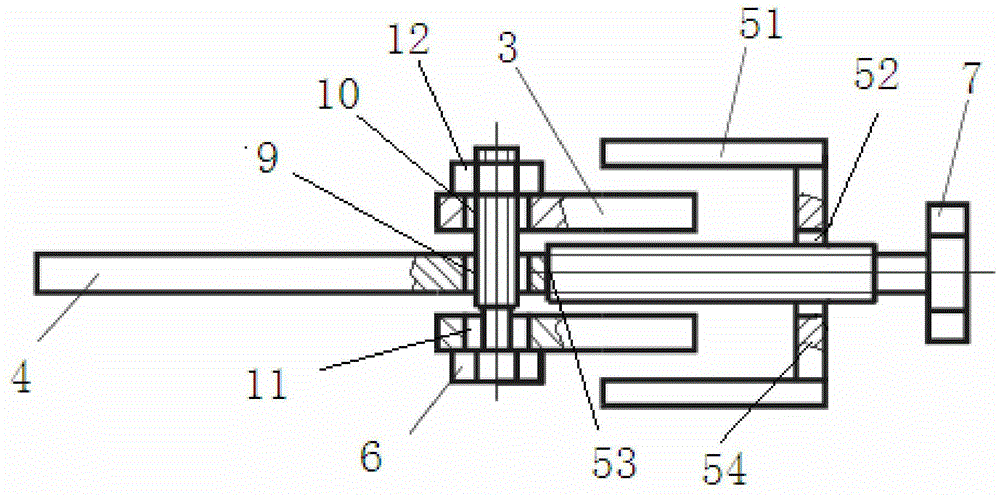
[0017] Such as figure 1 , figure 2 As shown, a rotary kiln for cement production includes a cylindrical barrel 1 coaxially installed on the inner side, a cylindrical cold air jacket 2 on the outer side, and an outer cylindrical surface of the barrel 1 and an inner cylindrical surface of the cold air jacket 2 A connecting structure is provided between the connecting structure. The connecting structure includes a first connecting plate 4 and a second connecting plate 3. The first connecting plate 4 is connected to the cylindrical surface of the kiln shell body, and the second connecting plate 3 is connected to the inside of the cold air jacket. Cylindrical surface connection, the first connecting plate 4 is provided with a first connecting hole 9, the second connecting plate is provided with a second c...


PUM


Abstract

The invention discloses a rotary kiln for cement production. The rotary kiln comprises a cylindrical tube body and a cylindrical cold air sleeve in coaxial arrangement, wherein the cylindrical tube body is arranged at the inner side, the cold air sleeve is arranged at the outer side, a connecting structure is arranged between the outer cylindrical surface of the tube body and the inner cylindrical surface of the cold air sleeve, and comprises a first connecting plate and a second connecting plate, the first connecting plate is connected with the outer cylindrical surface of the kiln tube body, the second connecting plate is connected with the inner cylindrical surface of the cold air sleeve, the first connecting plate is provided with a first connecting hole, the second connecting plate is provided with a second connecting hole, the position of the first connecting hole is matched with the position of the second connecting hole, and the first connecting plate and the second connecting plate are connected through the first connecting hole, the second connecting and screw nut and screw combinations. The rotary kiln has the advantages that the structural intensity is good, the reliability is high, the connecting part fracture problem due to stress concentration is avoided, the equipment fault is reduced, the equipment operation rate of the rotary kiln is improved, the use and maintenance cost is reduced, the maintenance workload of maintenance personnel is also reduced, and reliable guarantee is provided for stable production.

Description

Technical field [0001] The invention relates to the technical field of cement production equipment, in particular to a rotary kiln for cement production. Background technique [0002] The cold air jacket of the rotary kiln for cement production in the prior art includes two semi-arc structures. The two semi-arc structures are assembled and butted to form a cylindrical shape, and then steel plates are used as connecting ribs to be directly welded to the kiln shell. The problem with this kind of welding structure is that due to working in a high-temperature environment, after the equipment is used for a period of time, due to the temperature change during the operation or shutdown of the rotary kiln, the parts frequently expand and contract with heat, causing the weld to open or connect the ribs. Fracture, and each time the welding fracture occurs at the weakest position, which affects the normal operation of the equipment system. In severe cases, the components are displaced and f...

Claims


Application Information

Patent Timeline
IPC IPC(8): F27B7/20
Inventor 乔树政
Owner ZHANGQIU HUAMING CEMENT
Learn More