
Composite shear wall with super-thick steel plate

A technology of combining shear walls and thick steel plates, applied in the direction of walls, building components, buildings, etc., can solve problems such as insufficient to ensure the joint work of concrete, high difficulty in construction of steel bars through steel plates, and difficulty in ensuring construction quality, so as to enhance anti-slippage. Shifting ability, improving connection quality, and constructing simple effects

Active Publication Date: 2015-02-18
CHINA ARCHITECTURE DESIGN & RES GRP CO LTD
View PDF5 Cites 1 Cited by
  • Summary
  • Abstract
  • Description
  • Claims
  • Application Information

AI Technical Summary

Problems solved by technology

Its main disadvantages are: the reinforced concrete walls on both sides of the steel plate are relatively thick, and the shear studs are short, which is not enough to ensure the joint work between the concrete and the steel plate in the area other than the studs; holes, and the holes lead to the weakening of the steel plate. At the same time, the steel bars piercing the plate are all equipped with hooks. The construction of the steel bars passing through the steel plate is difficult, the construction quality is difficult to guarantee, the construction progress is slowed down, and the construction cost is increased.

Method used


Image

  • Composite shear wall with super-thick steel plate
  • Composite shear wall with super-thick steel plate
  • Composite shear wall with super-thick steel plate

Examples


Embodiment Construction

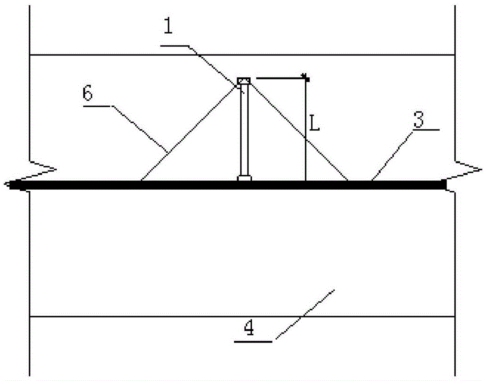
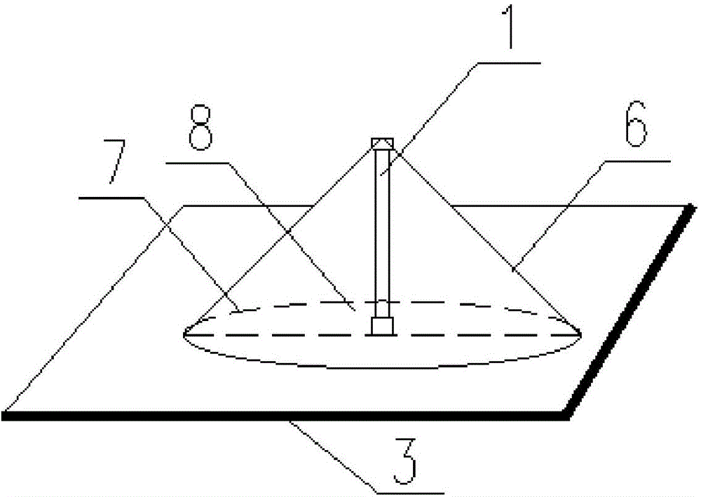
[0029] Refer to attached figure 1 It can be seen that the super-thick steel plate composite shear wall of the present invention includes a reinforced concrete wall 4 and an ultra-thick steel plate 3 embedded in the concrete wall 4, and long studs 1 are evenly arranged on both sides of the ultra-thick steel plate 3, and the long studs 1 Universal short pegs 2 are evenly arranged between them. The long stud 1 can be fixedly connected to the steel plate 3 through a steel bar connector, and the general short stud 2 can be fixedly connected to the steel plate 3 by welding or the like.

[0030] In order to ensure that the free end of the long stud 1 is within the outermost steel mesh of the concrete wall 4 and that the long stud 1 does not affect the pouring of concrete, the length of the long stud 1 is L≤h-a, where h represents the long stud The thickness of the concrete wall on the side where a represents the thickness from the outermost steel mesh to the outer surface of the wal...


PUM


Abstract

The invention discloses a composite shear wall with a super-thick steel plate. The composite shear wall comprises a concrete wall body and the super-thick steel plate embedded into the concrete wall body, wherein two sides of the super-thick steel plate are both evenly provided with long studs; general short studs are evenly arranged between every two adjacent long studs; the length L of each long stud is that L is less than or equal to h-a and more than d, wherein d is the length of each general short stud, h is the thickness of the concrete wall body on which the long studs are positioned, and a is the thickness from the outmost layer of reinforcing mesh to the outer surface of the wall body in the concrete wall body. According to the composite shear wall, mechanical bit force and friction force between the steel plate and concrete can be enhanced by the long studs, the area of the concrete is prevented from being increased by a long stud anchoring area, the steel plate and the concrete wall bodies on two sides are prevented from separating to enhance a joint function of the steel plate and the concrete wall bodies, and a technical scheme that the long studs and the short studs are mixed is adopted to improve the integrality of the composite shear wall of the steel plate. The composite shear wall of the super-thick steel plate has the advantages of definite force transferring, simple construction, convenience in construction and good integral ductility of a construction member and is favorable for improvement of the connection quality.

Description

technical field [0001] The invention relates to the technical field of structural engineering, in particular to an ultra-thick steel plate combined shear wall. Background technique [0002] The steel plate composite shear wall has the advantages of high bearing capacity, light weight, fast construction speed and good shear performance, and is especially suitable for high-rise and super high-rise buildings and seismic reinforcement projects in high-intensity areas. The superior performance in seismic performance makes it widely used in the field of super high-rise buildings. However, the research on steel plate composite shear walls is not mature at home and abroad. There are no relevant calculation provisions in the code for the connection method of steel plate and concrete, and the connection structure of steel plate and concrete directly affects the interaction between the two and the stability of the structure. And safety, but also affect the amount of structural steel a...

Claims


Application Information

Patent Timeline
IPC IPC(8): E04B2/00E04B2/84
Inventor 范重王义华杨开王金金
Owner CHINA ARCHITECTURE DESIGN & RES GRP CO LTD
Learn More