
A clamping device for LED lamp heat sink

A technology of clamping device and LED lamp, applied in the direction of injection device, etc., can solve the problems of slow processing speed and can not meet batch processing production, etc., and achieve the effects of convenient operation, simple structure and fast processing speed

Inactive Publication Date: 2016-08-24
SUZHOU CHENGYUAN PHOTOELECTRIC TECH
View PDF6 Cites 1 Cited by
  • Summary
  • Abstract
  • Description
  • Claims
  • Application Information

AI Technical Summary

Problems solved by technology

[0002] In the processing process of the LED lamp radiator in the prior art, it is generally handled with care manually. During the painting process, since the surface is coated with paint, when it is held by hand, the wet paint will stick to it. In the hands of workers, there is already a clamping device, but this clamping device can only be operated once by each worker, and the processing speed is slow, which cannot meet the needs of mass processing and production

Method used


Image

  • A clamping device for LED lamp heat sink

Examples


Embodiment Construction

[0013] In order to deepen the understanding of the present invention, the present invention will be described in further detail below in conjunction with the accompanying drawings and embodiments, which are only used to explain the present invention and do not limit the protection scope of the present invention.

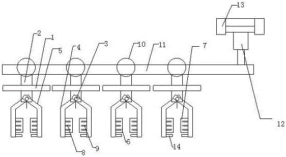
[0014] like figure 1 As shown, the present invention is a clamping device for LED lamp heat sinks. The clamping device includes several clamping devices, preferably 10 clamping devices, and the clamping devices can be arranged symmetrically from left to right to facilitate clamping. More radiators to improve work efficiency, each clamping device includes a limit plate 1, through the middle of the limit plate 1, a tension plate 2 is slidably arranged on the limit plate 1, the The tension plate 2 moves up and down in the limit plate 1, and a sliding column 3 is arranged on the tension plate 2, and two sliding columns are arranged on the tension plate 2 and pass throug...


PUM


Abstract

The invention discloses a holding device of an LED lamp radiator. The holding device comprises multiple clamping devices. Each clamping device comprises a limiting plate, wherein a tension plate penetrates through the middle of the limiting plate and is arranged on the limiting plate in a limiting manner; a sliding column is arranged on the tension plate; a left clamping plate and a right clamping plate are arranged on the tension plate, penetrate through the sliding column, and can move within the sliding column; a left semicircular clamping plate is arranged on the left clamping plate; a right semicircular clamping plate is arranged on the right clamping plate; multiple left chucks are arranged in the left semicircular clamping plate; multiple right chucks are arranged in the right semicircular clamping plate; a pull ring is arranged above each limiting plate; cross bars are arranged in the pull rings on the multiple clamping devices in a penetrating manner; an air cylinder capable of lifting or descending each of the cross rods is arranged at one end of the corresponding cross bar. The clamping device can effectively take material for the radiator subjected to paint spraying, does not dirty operating hands, mechanically feed and discharge materials, is high in processing speed, and improves the working efficiency.

Description

technical field [0001] The invention belongs to the technical field of LEDs, and in particular relates to a clamping device for a heat sink of an LED lamp. Background technique [0002] In the processing process of the LED lamp radiator in the prior art, it is generally handled with care manually. During the painting process, since the surface is coated with paint, when it is held by hand, the wet paint will stick to it. In the hands of workers, there is already a clamping device, but each worker can only operate this clamping device once, and the processing speed is slow, which cannot meet the needs of batch processing and production. Contents of the invention [0003] In order to solve the above problems, the present invention provides a device capable of clamping LED lamp heat sinks in large quantities, and the processing speed is fast. [0004] In order to achieve the above object, the present invention is achieved through the following technical solutions: [0005] ...

Claims


Application Information

Patent Timeline
Patent Type & Authority Patents(China)
IPC IPC(8): B05B13/02
CPCB05B13/0292
Inventor 戴岳平
Owner SUZHOU CHENGYUAN PHOTOELECTRIC TECH
Learn More