Edge light-type surface light source device and illumination device
一种照明装置、面光源的技术,应用在照明装置、光源、电光源等方向,达到长度缩短的效果
- Summary
- Abstract
- Description
- Claims
- Application Information
AI Technical Summary
Problems solved by technology
Method used
Image

Examples
no. 1 approach
[0113] First, use figure 1 with figure 2 Next, the surface light source device 10 of the first embodiment as an example of the edge-light type surface light source device of the present invention will be described.
[0114] (Structure of surface light source device)
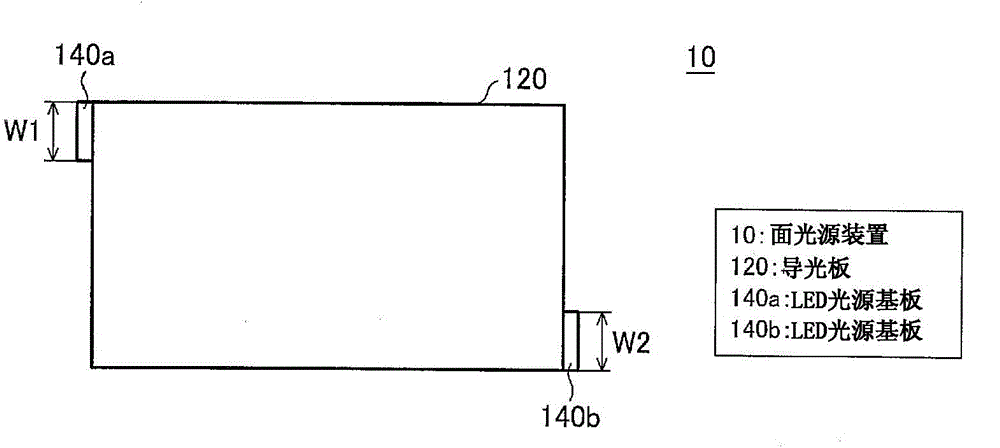
[0115] figure 1 The configuration of the surface light source device 10 according to the first embodiment of the present invention is schematically shown. figure 1 The illustrated surface light source device 10 includes a light guide plate 120 and LED light source substrates 140a and 140b. This surface light source device 10 is a so-called edge-light type surface light source device that irradiates light from the side of the light guide plate 120 to the interior of the light guide plate 120 using LED light source substrates 140 a and 140 b disposed on the side surfaces of the light guide plate 120 .
[0116] The light guide plate 120 corresponds to the shape of the liquid crystal display panel mounted in ...
no. 2 approach
[0150] Next, use image 3 with Figure 4 Next, the surface light source device 30 of the second embodiment as an example of the edge-light type light source substrate of the present invention will be described.
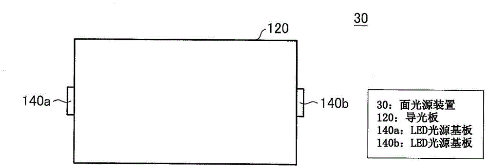
[0151] image 3 The configuration of the surface light source device 30 according to the second embodiment of the present invention is schematically shown. In the surface light source device 30 of the second embodiment, the arrangement of the LED light source boards is different from that of the surface light source device 10 , and is the same as that of the surface light source device 10 in other respects.
[0152] Specifically, as image 3 As shown, in the surface light source device 30 of the second embodiment, the LED light source substrate 140a is disposed at the left central portion of the light guide plate 120 , and the LED light source substrate 140b is disposed at the right central portion of the light guide plate 120 .
[0153] Figure 4 In the surface ...
no. 3 approach
[0161] Next, use Figure 5 with Image 6 Next, a surface light source device 50 according to a third embodiment as an example of the edge-light type light source substrate of the present invention will be described.
[0162] Figure 5 The configuration of the surface light source device 50 according to the third embodiment of the present invention is schematically shown. The surface light source device 50 of the third embodiment differs from the surface light source devices 10 and 30 in the arrangement of the LED light source boards, and is the same as the surface light source devices 10 and 30 in other respects.
[0163] Specifically, as Figure 5 As shown, in the surface light source device 50 of the third embodiment, the LED light source substrate 140a is disposed on the upper left end of the light guide plate 120 , and the LED light source substrate 140b is disposed on the lower right end of the light guide plate 120 . That is, in the surface light source device 50 of ...
PUM
 Abstract
Description
Claims
Application Information
 - Generate Ideas
- Intellectual Property
- Life Sciences
- Materials
- Tech Scout
- Unparalleled Data Quality
- Higher Quality Content
- 60% Fewer Hallucinations
Browse by: Latest US Patents, China's latest patents, Technical Efficacy Thesaurus, Application Domain, Technology Topic, Popular Technical Reports.
© 2025 PatSnap. All rights reserved.Legal|Privacy policy|Modern Slavery Act Transparency Statement|Sitemap|About US| Contact US: help@patsnap.com