High-efficiency aeration device for micro-nano bubbles in water body in riverway and use method of high-efficiency aeration device

A technology of micro-nano bubbles and aeration devices, which is applied in chemical instruments and methods, biological water/sewage treatment, water/sludge/sewage treatment, etc. problems, to achieve the effects of sufficient water contact range, low operating pressure, and high oxygen utilization.

Pending Publication Date: 2021-07-09
宁波碧城生态科技有限公司
View PDF6 Cites 1 Cited by
  • Summary
  • Abstract
  • Description
  • Claims
  • Application Information

AI Technical Summary

Problems solved by technology

[0004] The present invention intends to provide a high-efficiency aeration device for micro-nano bubbles in the water body in the river channel to solve the problem that a large number of foamy floating flocs are generated on the river surface in the existing river channel aeration technology, which affects the cleaning effect of the surface of the river channel water body

Method used


Image

  • High-efficiency aeration device for micro-nano bubbles in water body in riverway and use method of high-efficiency aeration device
  • High-efficiency aeration device for micro-nano bubbles in water body in riverway and use method of high-efficiency aeration device

Examples


Embodiment 1

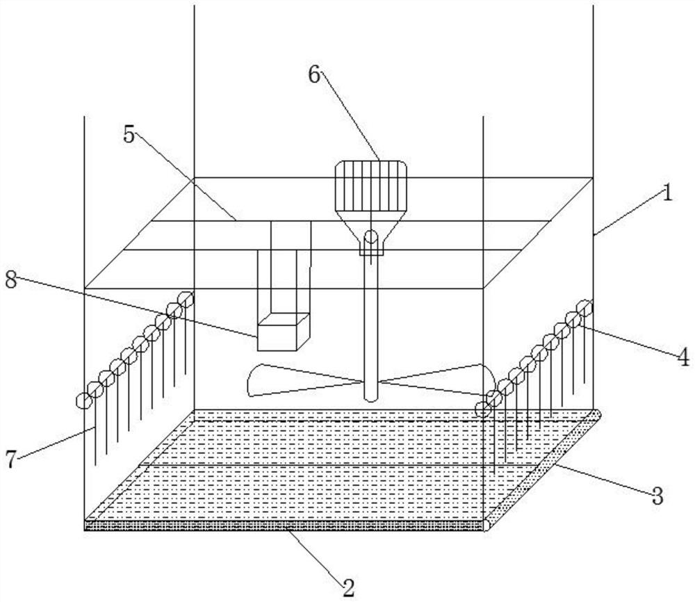
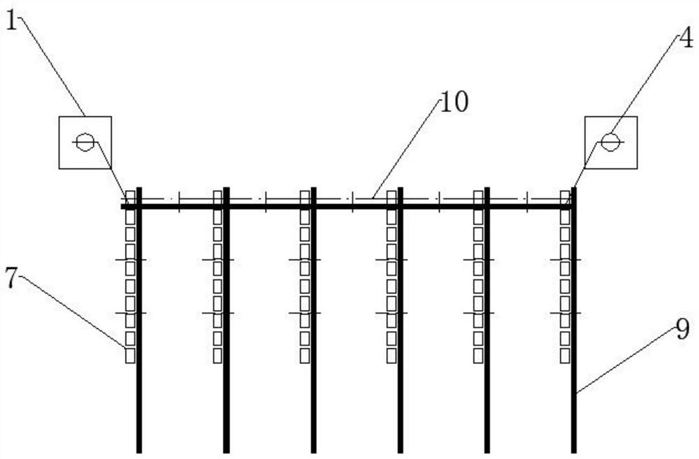
[0022] Embodiment 1, basically as attached figure 1 Shown: a high-efficiency aeration device for micro-nano bubbles in water in a river channel, including a rectangular bottom plate, four anchor rods 1 are welded on the four corners of the bottom plate, and 0.1 μm flat plates are welded on the bottom plate between the four anchor rods 1 Ceramic ultrafiltration membrane2. The flat ceramic ultrafiltration membrane 2 is connected with a compressed air pipeline 3, and a socket is provided on the wall of the compressed air pipeline 3 in the extension direction, and a sealing strip is bonded in the socket, and the flat ceramic ultrafiltration membrane 2 is inserted in the socket, and the sealing strip makes the flat plate The ceramic ultrafiltration membrane 2 is seamlessly connected with the compressed air pipeline 3, the compressed air pipeline 3 is connected with a check valve, and the check valve is connected with an air pump. The top of the flat ceramic ultrafiltration membran...

Embodiment 2

[0023] Embodiment 2, a method for using a high-efficiency aeration device for micro-nano bubbles in water in a river channel, using a suspension mechanism to suspend the device as a whole in the water body of the river channel, and using an air pump to inflate the flat ceramic ultrafiltration membrane 2 through the compressed air pipeline 3 , the flat ceramic ultrafiltration membrane 2 discharges some air bubbles after filtering the compressed air, and the stirrer 6 agitates the water flow to cut the air bubbles discharged from the flat ceramic ultrafiltration membrane 2 to produce uniformly diffused micro-nano bubbles. The micro-nano bubbles account for the proportion of the total amount of bubbles 25%, the micro-nano bubbles generated by the flat ceramic ultrafiltration membrane 2 will not condense, and follow the water flow to evenly disperse in the water body and float upward. In the process of stirring the water flow by the mixer 6, the medicine box 8 puts the microbial st...


PUM

PropertyMeasurementUnit
pore sizeaaaaaaaaaa

Abstract

The invention discloses a high-efficiency aeration device for micro-nano bubbles in a water body in a riverway and a use method of the high-efficiency aeration device in the field of aeration of the water body in the riverway. A flat plate ceramic ultrafiltration membrane on a bottom plate is 0.1 [mu]m and is seamlessly connected with a compressed air pipeline. A saw-shaped disc spiral stirrer is arranged above the device, high-speed water flow is formed on the surface of the saw-shaped disc spiral stirrer by utilizing spiral centrifugal force generated by the stirrer, and micro-compressed bubbles filtered by a 0.1 [mu]m ultrafiltration membrane are hydraulically cut to generate a large number of micro-nano micro-bubbles. The floating ball is arranged on the anchoring rod, so that the anchoring rod floats in a water body, river sediment is prevented from floating upwards, the oxygen utilization rate in the water is greatly increased, microbial strain agents are uniformly dispersed into the water body under the action of spiral centrifugal force, and a great effect is achieved on repairing of the water body.

Description

technical field [0001] The invention relates to the field of river water body aeration, in particular to a high-efficiency micro-nano bubble aeration device for water body in a river and a method for using the same. Background technique [0002] With the development of society, the pollution caused by industry, agricultural production and rapid population growth has increased year-on-year. When the speed of pollution entering the river is greater than the self-purification ability of the river itself, it is easy to lead to the formation of black and smelly rivers. River aeration technology is an effective measure to restore the ecological environment and self-purification ability of the river. [0003] At present, there are many micro-nano aeration methods on the market, among which the traditional micro-nano bubble generator is commonly used, the equipment is huge and the installation is cumbersome, the energy consumption of the equipment is huge, and the noise generated d...

Claims


Application Information

Patent Timeline
Patent Type & Authority Applications(China)
IPC IPC(8): C02F3/10
CPCC02F3/102C02F2103/007Y02W10/10
Inventor 郁建红刘亮赵燎原章建伟许宁宁应旭波
Owner 宁波碧城生态科技有限公司
Why Eureka
Try Eureka