
Test structure and test method of time dependent dielectric breakdown

A technology of test structure and test method, which is applied in the direction of test dielectric strength, etc., can solve the problems such as the decline of TDDB performance and the inability to evaluate it well, and achieve the effect of simple test structure

Active Publication Date: 2015-02-11
SEMICON MFG INT (SHANGHAI) CORP
View PDF5 Cites 4 Cited by
  • Summary
  • Abstract
  • Description
  • Claims
  • Application Information

AI Technical Summary

Problems solved by technology

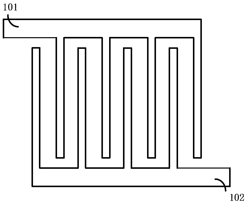
The test method is as follows: in the stress state, the first test piece 101 applies a stress voltage, and the second test piece 102 is grounded; in the measurement state, the first test piece 101 applies a voltage Vop, and the second test piece 102 The test piece 102 is grounded, and the TDDB performance of the device is evaluated through the two states, but this test structure cannot evaluate the degradation of TDDB performance due to the high-resistance (High-R) Joule heating effect (Joule heating effect)
[0006] Therefore, as semiconductor devices shrink, the high-resistance (High-R) Joule heating effect (Joule heating effect) has an increasing impact on TDDB performance, but the test structure in the prior art cannot evaluate the high-resistance (High-R) very well. R) The influence of Joule heating effect on TDDB performance, so it is necessary to improve the test structure in the prior art to solve the above problems and improve the performance and yield detection capabilities of the device

Method used


Image

  • Test structure and test method of time dependent dielectric breakdown
  • Test structure and test method of time dependent dielectric breakdown
  • Test structure and test method of time dependent dielectric breakdown

Examples


Embodiment 1

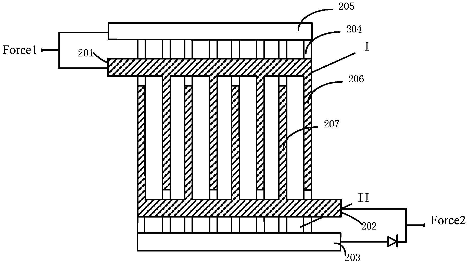
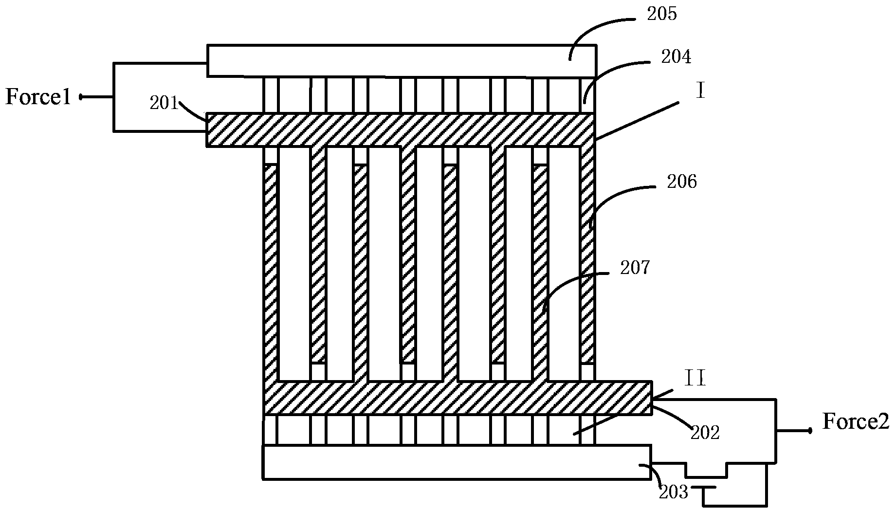
[0064] In this example, if Figure 2a As shown, the resistor array unit and the test unit are arranged in parallel with a metal dielectric layer between them to isolate the resistor array unit and the test unit.

[0065] The size of the resistance wire in the resistance array sheet is the same as the size of the comb teeth in the test unit or the size of the serpentine bending test piece, so as to ensure that the heat generated by the resistance wire is better transferred to the test unit. The size of the resistance wires in the resistance array sheet is set in alignment with the comb teeth in the test unit.

[0066] The resistance array unit II includes a first connection line 205 and a second connection line 203 and a resistance line 204 between the first connection line 205 and the second connection line 203, the resistance line 204 connects the first The connection line 205 and the second connection line 203 are connected as a whole, wherein the resistance lines are arrang...

Embodiment 2

[0070] In this embodiment, the test unit includes a comb-shaped test piece and a serpentine-shaped test piece located on the same plane, the two test pieces are arranged oppositely, and the comb-shaped structure test piece has a plurality of conductive combs teeth, the serpentine-bent test piece is bent around the conductive comb, and the conductive comb is embedded in the bend.

[0071] Other structures and working principles are the same as in Embodiment 1.

Embodiment 3

[0073] In this example, if Figure 2a As shown, the resistor array unit and the test unit are arranged in parallel with a metal dielectric layer between them to isolate the resistor array unit and the test unit.

[0074] The size of the resistance wire in the resistance array sheet is exactly the same as the size of the comb teeth in the test unit or the size of the serpentine bending test piece, so as to ensure that the heat generated by the resistance wire is better transferred to the test unit. The size of the resistance wires in the resistance array sheet is set in alignment with the comb teeth in the test unit.

[0075] The resistance array unit II includes a first connection line 205 and a second connection line 203 and a resistance line 204 between the first connection line 205 and the second connection line 203, wherein the resistance line is vertically arranged, and There is a certain interval between the resistance lines 204, wherein the first connection line 205, ...


PUM


Abstract

The invention relates to a test structure and test method of a time dependent dielectric breakdown (TDDB). The test structure includes a test unit, a resistor array unit and a control unit, wherein the test unit is above the resistor array unit and a metal medium layer is arranged between the test unit and the resistor array unit. The resistor array unit and the control unit are serially connected and then arranged in parallel with the test unit between a first connection end and a second connection end. Through application of different voltages between the first connection end and the second connection end, the control unit controls the stress state at work or non-work measurement state of the resistor array unit and through the two kinds of states, effects of joule heat of the resistor array unit on the electric breakdown performance of the metal medium layer are evaluated and the effects of the joule heat of the resistors on the reliability of the metal medium layer in a real integrated circuit are simulated authentically. The test structure and test method solve a defect that TDDB performance, caused by a joule heat effect, cannot be evaluated in the prior art and improve the detection capability of the performance and yield of a device.

Description

technical field [0001] The invention relates to the field of semiconductors, in particular, the invention relates to a TDDB test structure and a test method. Background technique [0002] With the continuous development of integrated circuit technology, more devices will be integrated on the chip, and the chip will adopt faster speed. Driven by these requirements, the geometric size of devices will continue to shrink, and new materials, new technologies and new manufacturing processes will be continuously used in the chip manufacturing process. These improvements have a great impact on the life of a single device, which may result in increased vulnerability of local areas, increased power density, increased device complexity, and the introduction of new failure mechanisms. must be considered at the outset, and monitored and tested throughout the development and manufacturing of the device, all the way to the completion of the final product. [0003] With the continuous red...

Claims


Application Information

Patent Timeline
IPC IPC(8): G01R31/12
Inventor 冯军宏
Owner SEMICON MFG INT (SHANGHAI) CORP
Learn More