
Equipment system fault integral diagnosis method and device

A system failure and comprehensive diagnosis technology, applied in the field of test engineering, can solve problems such as abnormal operation of equipment systems, impact on task execution, economic losses, etc., to reduce maintenance manpower and other support resources, improve accuracy and scientificity, The effect of reducing life cycle costs

Inactive Publication Date: 2015-02-11
中国船舶重工集团公司第七二六研究所
View PDF6 Cites 11 Cited by
  • Summary
  • Abstract
  • Description
  • Claims
  • Application Information

AI Technical Summary

Problems solved by technology

[0002] With the continuous increase of equipment system functions, the system structure is becoming more and more complex, any small fault may cause the equipment system to malfunction, and even directly lead to equipment damage, resulting in immeasurable economic losses and affecting task execution
[0003] The traditional equipment system focuses on the realization of functions, the design of testing technology is simple, the fault location is difficult, the ambiguity is high, and the maintenance manual cannot cover all the conditions, and it is inconvenient for the operator to query numerous maintenance manuals. Insufficient, leading to various problems such as long fault diagnosis time, high use and maintenance support costs, and insufficient maintenance manpower
On the other hand, after the equipment system has been tested or repaired, the staff often record the operation process in paper on site, or fill in the report (or write a report) after returning to the unit. The fault recording process is not timely or even not recorded, and there is a lack of fault Unified standards for recording, resulting in arbitrariness of fault records and loss of fault data

Method used


Image

  • Equipment system fault integral diagnosis method and device
  • Equipment system fault integral diagnosis method and device
  • Equipment system fault integral diagnosis method and device

Examples


Embodiment Construction

[0056] The present invention will be described in detail below in conjunction with specific embodiments. The following examples will help those skilled in the art to further understand the present invention, but do not limit the present invention in any form. It should be noted that those skilled in the art can make several modifications and improvements without departing from the concept of the present invention. These all belong to the protection scope of the present invention.

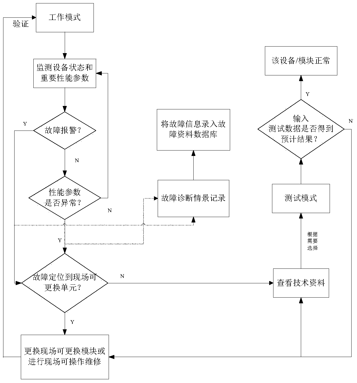
[0057] According to the equipment system fault comprehensive diagnosis method provided by the present invention, it includes two stages of working mode and test mode, wherein, the working mode stage includes steps 1-4, and the test mode stage includes steps 5-6. After the work item) is over, the operator can choose whether to enter the working mode stage according to actual needs. Specifically, each step is as follows:

[0058] Step 1: Monitor the equipment status and performance parameters of th...


PUM


Abstract

The invention provides an equipment system fault integral diagnosis method and device. An integral diagnosis technology is applied to an equipment system, the important performance parameters of safe and critical functions of the equipment system and the state of each equipment and filed replaceable module can be monitored, when the fault occurs, on-line technical data is used, in addition, the fast detection and isolation on the fault is realized in a test mode, the fault diagnosis scene process is recorded in real time and is repeated through the fault recording and repeating function, and relevant contents such as fault data information and processing methods are recorded and stored through a built fault data database. The method and the device provided by the invention has the advantages that the goal of economic and effective detection and non-fuzzy isolation of equipment system fault can be realized, the task requirements can be met, meanwhile, data and experience are accumulated for the subsequent test and maintenance through recording and storing the fault information, and the combat readiness completeness, the task success performance and the safety of the equipment system are improved.

Description

technical field [0001] The invention belongs to the technical field of testable engineering, in particular to the application of testable design technology (comprehensive diagnosis) in equipment systems, in particular to a method and device for comprehensive diagnosis of equipment system faults. Background technique [0002] With the continuous increase of the functions of the equipment system, the system structure is becoming more and more complex. Any small failure may cause the equipment system to malfunction, or even directly cause damage to the equipment, causing immeasurable economic losses and affecting task execution. [0003] The traditional equipment system focuses on the realization of functions, the design of testing technology is simple, the fault location is difficult, the ambiguity is high, and the maintenance manual cannot cover all the conditions, and it is inconvenient for the operator to query numerous maintenance manuals. Insufficient, resulting in long f...

Claims


Application Information

Patent Timeline
Patent Type & Authority Applications(China)
IPC IPC(8): G01M99/00
Inventor 屈津竹刘本奇张倩倩
Owner 中国船舶重工集团公司第七二六研究所
Learn More