Pipe-penetrating work table

A workbench and pipe-through technology, which is applied to workbenches, metal processing, manufacturing tools, etc., can solve the problems of air conditioner cleanliness and quality problems, increased labor intensity, and reduced production efficiency, so as to ensure personal health and reduce labor intensity , the effect of improving production efficiency

Active Publication Date: 2015-02-11
GREE ELECTRICHEFEI +1
View PDF8 Cites 3 Cited by
  • Summary
  • Abstract
  • Description
  • Claims
  • Application Information

AI Technical Summary

Problems solved by technology

[0002] At present, the two components (condenser components, evaporator components) produced by our company are mainly composed of aluminum foil and U-tubes. The important tube-threading process is completed on the existing old-style tube-threading platform. Due to the structure of the old-style tube-threading platform Limitation, which has a serious impact on the efficiency and quality of pipe penetration
[0003] Problems existing in the old workbench: due to the different lengths of the two machine components produced in different models, when the two machine components of different models are piercing the pipe, the employees need to find a fixed position on the workbench, and the workbench cannot meet the requirements of fast Adjusting the vertical adjustment length function seriously affects the production efficiency when switching between different models; during the pipe threading operation, due to the out-of-round opening of some copper pipes, the pipe mouth after passing through the aluminum foil is covered with aluminum powder to varying degrees. These aluminum powders will bring serious quality problems to the cleanliness of the air conditioner. The components of the two devices passing through need to be purged again to clean the aluminum powder at each nozzle. It also wastes a lot of manpower, reduces production efficiency and increases labor intensity, and at the same time, prolonged exposure to aluminum powder will cause occupational health hazards

Method used


Image

  • Pipe-penetrating work table
  • Pipe-penetrating work table
  • Pipe-penetrating work table

Examples


Embodiment Construction

[0024] It should be noted that, in the case of no conflict, the embodiments in the present application and the features in the embodiments can be combined with each other. The present invention will be described in detail below with reference to the accompanying drawings and examples.

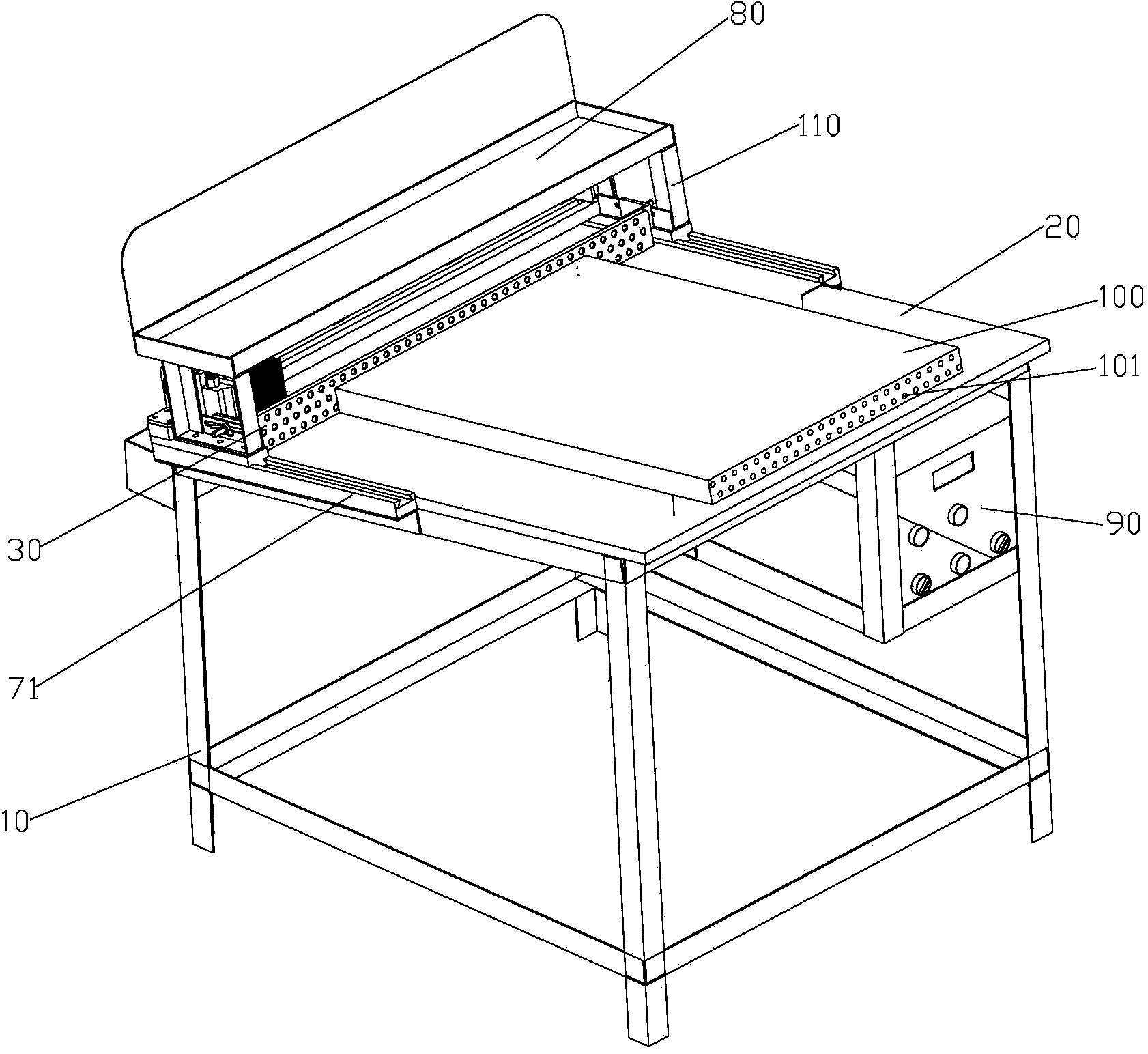
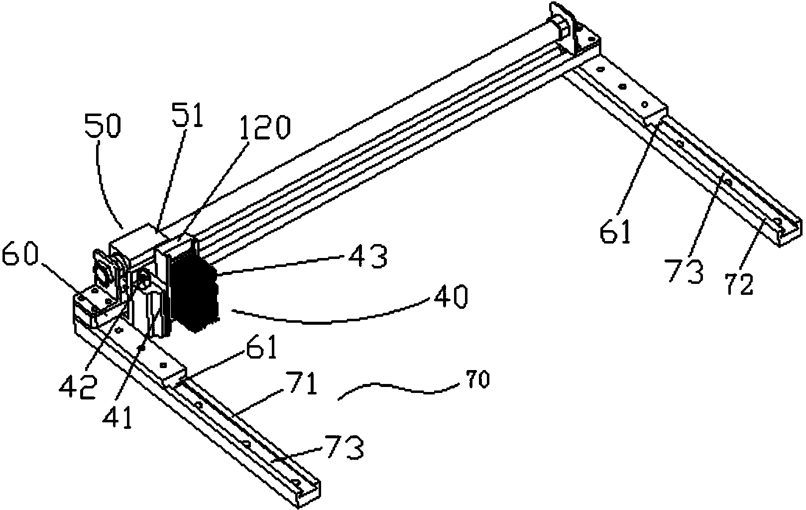
[0025] see Figure 1 to Figure 4 As shown, according to the embodiment of the present invention, a pipe threading workbench is provided. The pipe passing workbench includes a support frame 10 , a workbench 20 , a positioning plate 30 , a purging assembly 40 and a driving device 50 . Wherein, the workbench 20 is set on the support frame 10 to place the aluminum foil 100 to be worn; the positioning plate 30 is set on the workbench 20, and the positioning plate 30 is provided with a positioning hole 31 for positioning pipe fittings, and the aluminum foil 100 is provided with The mounting holes 101 for installing the pipe fittings are arranged in one-to-one correspondence; the purge assembly 40 i...


PUM


Abstract

The invention provides a pipe-penetrating work table. The pipe-penetrating work table comprises support frames, a work table which is arranged on the pipe-penetrating work table to be used for placing aluminum foil to be subjected to pipe penetration, a positioning plate which is arranged on the work table, a blowing component which is arranged on one side, which is away from the aluminum foil, of the positioning plate to blow the openings of pipe fittings, and a driving device which is arranged on the work table to drive the blowing component to move in the length direction of the positioning plate, wherein positioning holes which are used for positioning the pipe fittings are formed in the positioning plate, and the positioning holes and mounting holes which are formed in the aluminum foil to be used for mounting the pipe fittings are formed in a one-to-one correspondence manner. According to the pipe-penetrating work table disclosed by the invention, the manual labor strength in the pipe-penetrating process can be reduced, the production efficiency is improved, and the human body health of workers is ensured.

Description

technical field [0001] The present invention relates to the technical field of air conditioning, and more specifically, to a pipe threading workbench. Background technique [0002] At present, the two components (condenser components, evaporator components) produced by our company are mainly composed of aluminum foil and U-tubes. The important tube-threading process is completed on the existing old-style tube-threading platform. Due to the structure of the old-style tube-threading platform Limitations have a serious impact on the efficiency and quality of pipe penetration. [0003] Problems existing in the old workbench: due to the different lengths of the two machine components produced in different models, when the two machine components of different models are piercing the pipe, the employees need to find a fixed position on the workbench, and the workbench cannot meet the requirements of fast Adjusting the vertical adjustment length function seriously affects the produc...

Claims


Application Information

Patent Timeline
Patent Type & Authority Applications(China)
IPC IPC(8): B23P19/00B08B5/02
CPCB08B1/002B08B5/02B25H1/02
Inventor 高海涛邵丽国方健汪志春周留义张飞朱正伟刘发祥
Owner GREE ELECTRICHEFEI
Why Eureka
Try Eureka