Automatic blowing device inside loop

A looper, automatic technology, used in workpiece surface treatment equipment, metal rolling, manufacturing tools, etc., can solve the problems of rolling force damage to the rolling mill, blocking of rolling channels, fractures, etc.

Active Publication Date: 2015-02-11
JIANGSU YONGGANG GROUP CO LTD
View PDF6 Cites 2 Cited by
  • Summary
  • Abstract
  • Description
  • Claims
  • Application Information

AI Technical Summary

Problems solved by technology

Due to the use of various wheels such as supporting rollers, side rollers, pressure rollers and sleeve rollers, these wheels need to be cooled by flushing water. The accumulated water will cause the head of the steel bar to cool rapidly, and the steel bar will easily form blackheads when it meets water when it passes through. During the rolling process, the head of the hot slab is rapidly cooled due to accumulated water to form a black head), which is prone to breakage when entering the rolling mill, and is brought into the finishing mill to block the rolling channel, resulting in piled steel
Or due to the high hardness, a large rolling force is generated to damage the rolling mill

Method used


Image

  • Automatic blowing device inside loop

Examples


Embodiment Construction

[0016] In order to make the object, technical solution and advantages of the present invention clearer, the present invention will be further described in detail below in conjunction with the accompanying drawings and embodiments. It should be understood that the specific embodiments described here are only used to explain the present invention, not to limit the present invention. It should be noted that the words "front", "rear", "left", "right", "upper" and "lower" used in the following description refer to the directions in the drawings, and the words "inner" and "outer ” refer to directions towards or away from the geometric center of a particular part, respectively.

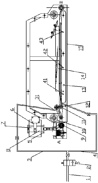
[0017] see figure 1 , The present invention relates to an automatic purging device inside a looper. The looper includes a bottom plate 15 and a side wall, and a reinforcement channel 14 is arranged above the bottom plate 15 . The two ends of the length direction of the side wall are provided with a steel b...


PUM

PropertyMeasurementUnit
diameteraaaaaaaaaa
diameteraaaaaaaaaa

Abstract

The invention relates to an automatic blowing device inside a loop. The loop comprises a bottom plate and a side wall, wherein a reinforcing steel bar channel is formed above the bottom plate; a reinforcing steel bar inlet and a reinforcing steel bar outlet are formed in the two ends of the side wall in the length direction; a support wheel, a pressing wheel and a loop release wheel are sequentially arranged inside the loop and at the inlet of reinforcing steel bars; the loop release wheel is connected with a cylinder and a loop release wheel electromagnetic valve; the automatic blowing device comprises a blowing pipeline arranged inside the loop; a membrane electromagnetic valve is arranged on the blowing pipeline; the blowing pipeline is divided into two paths, and each path is connected with a compressed air pipeline through the membrane electromagnetic valve; at least one air blowing hole is formed in each path of the blowing pipeline. The compressed air blowing pipeline is mounted on the reinforcing steel bar channel inside the loop, the blowing holes are respectively formed between the inlet and the outlet of the reinforcing steel bars, of the loop, air is supplied through two blowing pipelines, the accumulated water at the bottom of the loop can be greatly removed, and blackhead steel can be avoided.

Description

technical field [0001] The patent of the present invention relates to the technical field of steel rolling equipment, specifically adding an automatic purging device in the looper. Background technique [0002] In the production process of cold rolling, coating, etc., the accumulator is used to store incoming materials, and the time gap for storing incoming materials is used to weld the tail of the steel coil to the head of the next steel coil, so as to Realize continuous production. In the looper, the steel bar needs to be set up to eliminate the inconsistency of the line speed caused by rolling. Due to the use of various wheels such as supporting rollers, side rollers, pressure rollers and sleeve rollers, these wheels need to be cooled by flushing water. The accumulated water will cause the head of the steel bar to cool rapidly, and the steel bar will easily form blackheads when it meets water when it passes through. During the rolling process, the head of the hot slab ...

Claims


Application Information

Patent Timeline
Patent Type & Authority Applications(China)
IPC IPC(8): B21B45/02B21B41/00
Inventor 黄卫兵杨耀栋陈德祥
Owner JIANGSU YONGGANG GROUP CO LTD
Why Eureka
Try Eureka