Low-voltage cabinet of box-type transformer station, and box-type transformer station with same
What is Al technical title?
Al technical title is built by PatSnap Al team. It summarizes the technical point description of the patent document.
A technology for box-type substations and low-voltage cabinets, which is applied in substation/distribution device shells, substation/switch layout details, substation/switchgear boards/panels/desks, etc., which can solve the problem of increasing space, floor space, and space Problems such as low utilization rate and low operating efficiency achieve the effect of reducing the workload of disassembly and assembly, high space utilization rate, and improving operating efficiency
Active Publication Date: 2015-02-04
STATE GRID CORP OF CHINA +2
View PDF7 Cites 6 Cited by
Summary
Abstract
Description
Claims
Application Information
AI Technical Summary
This helps you quickly interpret patents by identifying the three key elements:
Problems solved by technology
Method used
Benefits of technology
Problems solved by technology
The low-voltage cabinet in the box-type substation with the above structure has the following defects in the actual use process: 1) When designing the cabinet, the installation of various components in the cabinet is considered separately, and the space in a single cabinet cannot be fully utilized. Low, which increases the area occupied by the overall space, and the corresponding box transformer should also consider increasing the space and floor area; 2) The cabinets need to be connected during assembly, and the cabinets need to be separated for maintenance. The workload of the workers is heavy, the labor intensity is high, the assembly and maintenance are inconvenient, the work efficiency is low, and it is not easy to guarantee the work quality
Method used
Image
Click on the blue label to locate the original text in one second.
Reading with bidirectional positioning of images and text.
Examples
Embodiment Construction
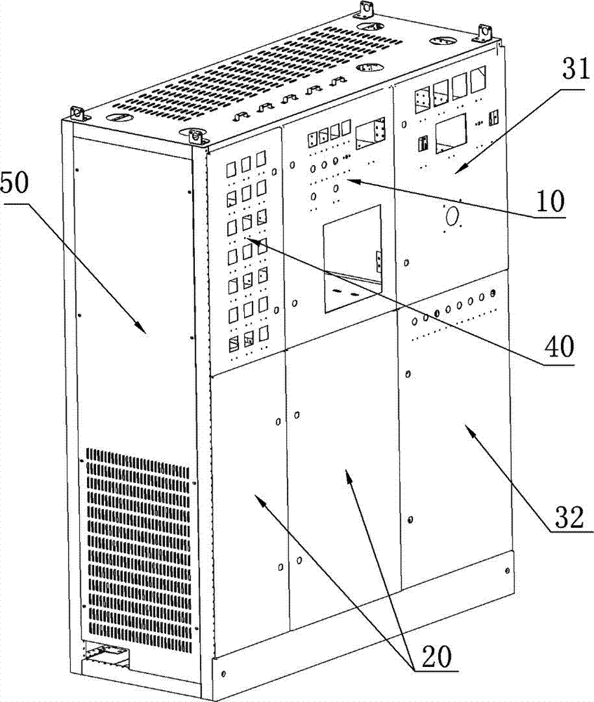
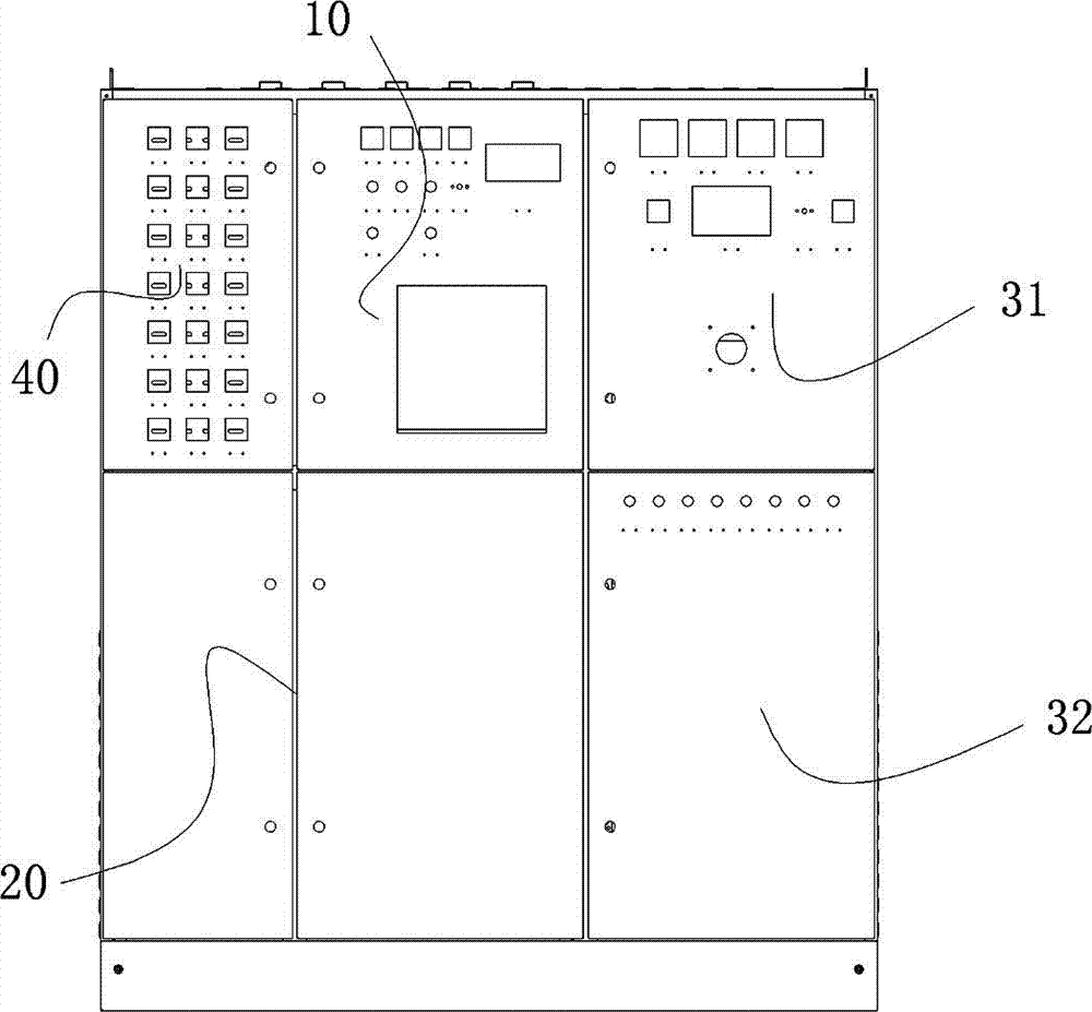
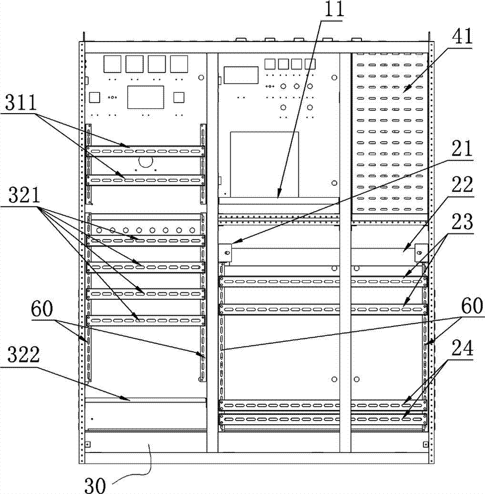
[0023] An embodiment of the low-voltage cabinet of the box-type substation in the present invention is as follows Figure 1~Figure 6 As shown, it is a low-voltage cabinet with the existing C profile as the skeleton, and the cabinet body is assembled through a bolt combination structure. The back of the low-voltage cabinet is open to form a structure without a rear door, and it is a structure without a bottom plate with an open bottom. Side protective partitions 50 are provided on both lateral sides of the cabinet body, and the inside of the cabinet body includes incoming line unit 10 , feeder line unit 20 , capacitance compensation unit 30 and secondary instrument unit 40 separated from each other by corresponding partition boards. The low-voltage cabinet adopts a structure without a bottom plate, which shares the bottom plate with the box-type transformer, and relies on the bottom plate of the box-type transformer for protection, which can save materials and reduce assembly o...
PUM
Abstract
The invention relates to a low-voltage cabinet of a box-type transformer station, and the box-type transformer station with same, wherein the low-voltage cabinet of the box-type transformer station comprises a wire inlet unit, a feeder line unit, a capacitance compensating unit and a secondary instrument unit. The wire inlet unit, the feeder line unit, the capacitance compensating unit and the secondary instrument unit are arranged in one cabinet body and furthermore are separated from one another through corresponding baffle plates. The wire inlet unit and the secondary instrument unit are parallelly arranged in the transverse direction of the cabinet body. The feeder line unit is arranged below the wire inlet unit and the secondary instrument unit. The capacitance compensating unit is arranged at one side of the wire inlet unit in the transverse direction, which deviates the secondary instrument unit, and furthermore the lower part of the capacitance compensating unit is arranged parallelly with the feeder line unit in the transverse direction. The wire inlet unit of the low-voltage cabinet is arranged at the middle part of the cabinet body in the transverse direction, thereby realizing convenient connection with other units. Furthermore the capacitance compensating unit and the feeder line unit can be distributed to relatively large spaces, thereby realizing reasonable layout and high space utilization rate. Furthermore, the units are arranged in a same cabinet body, thereby realizing benefit for assembling and maintenance, reducing detaching workload and improving operation efficiency.
Description
technical field [0001] The invention relates to a low-voltage cabinet of a box-type substation and a box-type substation. Background technique [0002] Box-type substation, referred to as box-type substation, is a compact power distribution equipment integrating high-voltage switchgear, distribution transformer and low-voltage power distribution device. It organically combines functions such as high-voltage power receiving, transformer step-down, and low-voltage power distribution. Together, they are installed in a moisture-proof, rust-proof, dust-proof, rodent-proof, fire-proof, theft-proof, heat-insulated, fully enclosed steel structure box, suitable for cities, rural areas, industrial and mining enterprises, public building facilities, oil and gas fields and wind power stations, etc. In many fields, it can replace the original civil power distribution room and substation, and become a new type of complete power transformation and distribution device, with small footprint,...
Claims
Application Information
Patent Timeline
Application Date:The date an application was filed.
Publication Date:The date a patent or application was officially published.
First Publication Date:The earliest publication date of a patent with the same application number.
Issue Date:Publication date of the patent grant document.
PCT Entry Date:The Entry date of PCT National Phase.
Estimated Expiry Date:The statutory expiry date of a patent right according to the Patent Law, and it is the longest term of protection that the patent right can achieve without the termination of the patent right due to other reasons(Term extension factor has been taken into account ).
Invalid Date:Actual expiry date is based on effective date or publication date of legal transaction data of invalid patent.