
Lightning protection connector assembly and equipment cabinet using the lightning protection connector assembly

A technology for connector components and equipment cabinets, which is applied in the direction of connection parts protective grounding/shielding devices, connection parts installation, connection, etc., can solve the problem of increasing the space occupied by lightning protection connector components, complex structure of lightning protection connector components, printing The heat dissipation effect of the plate making is not very good, etc., to achieve the effect of reducing the complexity of the structure

Active Publication Date: 2017-01-04
CHINA AVIATION OPTICAL-ELECTRICAL TECH CO LTD
View PDF5 Cites 0 Cited by
  • Summary
  • Abstract
  • Description
  • Claims
  • Application Information

AI Technical Summary

Problems solved by technology

The problem with the existing lightning protection connector assembly is that the panel connector is connected to the printed board through the first transfer connector, the printed board is connected to the cabinet main board through the second transfer connector, and the transfer module The setting of the lightning protection connector assembly not only makes the structure of the lightning protection connector assembly very complicated, but also greatly increases the production cost of the lightning protection connector assembly, and also increases the occupied space of the lightning protection connector assembly; between the panel connector and the printed board Lack of corresponding heat dissipation gap, the heat dissipation effect of the printed board is not very good, which affects the service life of the printed board and the entire lightning protection connector assembly

Method used


Image

  • Lightning protection connector assembly and equipment cabinet using the lightning protection connector assembly
  • Lightning protection connector assembly and equipment cabinet using the lightning protection connector assembly
  • Lightning protection connector assembly and equipment cabinet using the lightning protection connector assembly

Examples


Embodiment Construction

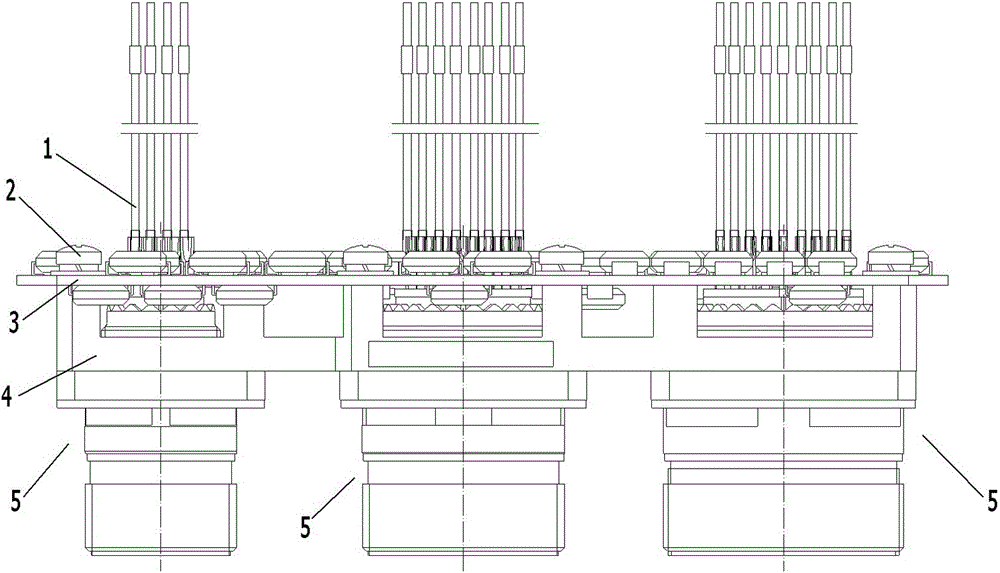
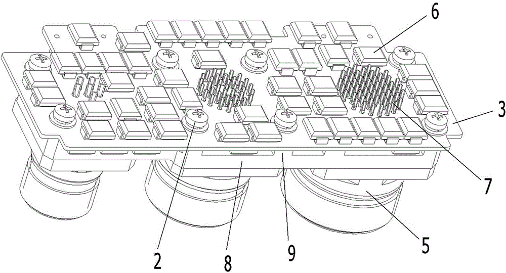
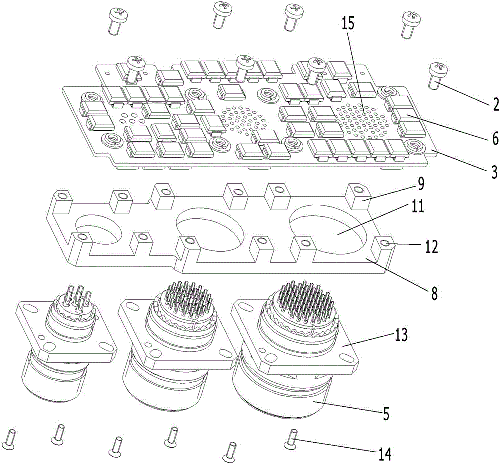
[0022] Examples of equipment cabinets such as Figure 1~5 As shown: it includes a chassis with a mounting panel and a cabinet mainboard (not shown in the figure) arranged inside the chassis, and also includes a lightning protection connector assembly for connecting external devices to the cabinet mainboard. Both the chassis and the cabinet mainboard belong to the prior art , its specific structure will not be described in detail here, and the installation panel is grounded. The lightning protection connector assembly includes a printed board 3 provided with a lightning protection circuit 6 and three panel connectors 5 arranged at intervals along the left and right directions. The lightning protection circuit belongs to the prior art, and its specific structure will not be described in detail here. A metal support frame 4 is arranged between the panel connector 5 and the printed board 3 . The panel connector 5 is located on the front side of the printed board 3, and the rear e...


PUM


Abstract

The invention relates to a lightning protection connector assembly and an equipment cabinet using the lightning protection connector assembly. The lightning protection connector assembly includes a printed board and at least one panel connector, the printed board is provided with a lightning protection circuit, and the panel connector is located on On the front side of the printed board, the rear end of the contact piece of the panel connector is provided with a soldering wire cup, and the printed board is provided with a perforation for the soldering wire cup to pass through, and the soldering wire cup has a The outer peripheral surface of the welding connection of the lightning protection circuit and the inner peripheral surface of the corresponding wire welding connection. The invention provides a lightning protection connector assembly with simple structure and low manufacturing cost and an equipment cabinet using the lightning protection connector assembly.

Description

technical field [0001] The invention relates to a lightning protection connector assembly and an equipment cabinet using the lightning protection connector assembly. Background technique [0002] Existing equipment cabinets include a cabinet with a mounting panel, and a cabinet main board is arranged inside the cabinet. During use, equipment outside the cabinet needs to be electrically connected to the cabinet main board through a lightning protection connector assembly. The existing lightning protection connector assembly such as the "lightning protection connector assembly" disclosed in Chinese patent CN202076616U, the lightning protection connector assembly includes a printed board provided with a lightning protection circuit and at least one panel for mounting on the installation panel Connector, the panel connector includes a connector housing with contacts inside, a transfer module electrically connected to the lightning protection circuit is provided on the printed bo...

Claims


Application Information

Patent Timeline
Patent Type & Authority Patents(China)
IPC IPC(8): H01R12/58H01R12/53H01R13/02H01R13/73H01R13/648
Inventor 赵飞飞陈跃平
Owner CHINA AVIATION OPTICAL-ELECTRICAL TECH CO LTD
Learn More