
Flow rate detection method for low-energy-consumption ultrasonic flow rate meter and system

A flow detection and ultrasonic technology, applied in the field of ultrasonic flowmeter design, can solve the problems of continuous vibration of the transducer, large system energy loss, inconvenient use, etc., and achieve the effects of reducing energy loss, improving measurement accuracy and prolonging service life

Active Publication Date: 2015-02-04
姜跃炜
View PDF4 Cites 12 Cited by
  • Summary
  • Abstract
  • Description
  • Claims
  • Application Information

AI Technical Summary

Problems solved by technology

In the prior art, the excitation signal used to excite the transducer is mostly a continuous signal, but since only the time of downstream or upstream is collected, the part after the continuous signal is basically not used, and the continuous excitation wave signal will cause the transducer The continuous vibration of the energy device leads to excessive energy loss of the system, requiring frequent battery replacement of the ultrasonic flowmeter, which is inconvenient to use
In addition, the continuous excitation signal will also generate interference waveforms on the pipe wall or other parts, which will affect the measurement accuracy of the ultrasonic flowmeter

Method used


Image

  • Flow rate detection method for low-energy-consumption ultrasonic flow rate meter and system
  • Flow rate detection method for low-energy-consumption ultrasonic flow rate meter and system
  • Flow rate detection method for low-energy-consumption ultrasonic flow rate meter and system

Examples


Embodiment Construction

[0016] Combine below Figure 1 to Figure 6 , The present invention is described in further detail.

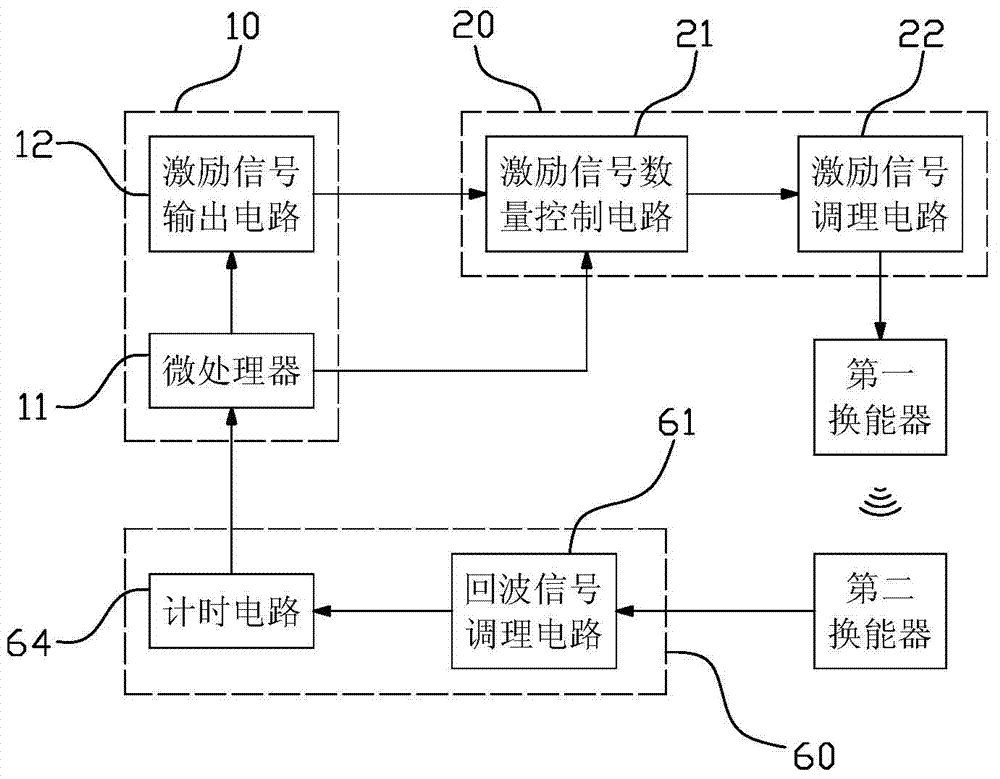
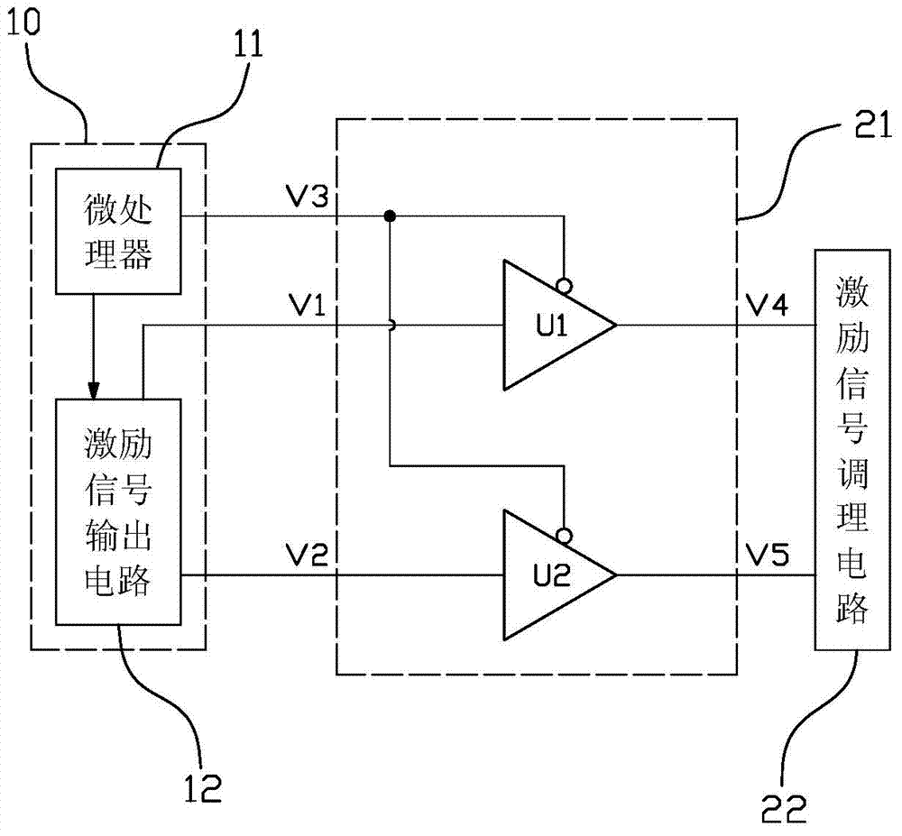
[0017] Refer to figure 2 , A flow detection method for a low-energy ultrasonic flow meter, including the following steps: (A) the main control module 10 generates a continuous excitation signal with a period of T and outputs it to the excitation signal quantity control circuit 21; (B) excitation signal The quantity control circuit 21 processes the excitation signal of the continuous period into the excitation signal of the specified number of cycles, and the specified period is greater than or equal to 6; (C) the first transducer emits ultrasonic waves after receiving the excitation signal of the specified number of cycles Signal; (D) the second transducer outputs the echo signal to the timing circuit 64 in the echo signal processing module 60 for timing after receiving the ultrasonic wave; (E) the timing circuit 64 outputs the result to the main control module 10, the main contr...


PUM


Abstract

The invention belongs to the technical field of ultrasonic flow rate meter design, and particularly relates to a flow rate detection method for a low-energy-consumption ultrasonic flow rate meter and a system realizing the method. The method comprises the following steps that a main control module generates continuous excitation signals with the period being T and outputs the excitation signals to an excitation signal number control circuit; the excitation signal number control circuit processes the continuous and periodic excitation signals into excitation signals in specific period numbers, and the specific period number is greater than or equal to 6; a first energy converter receives the specific period number of excitation signals and then sends ultrasonic signals; the second energy converter receives the ultrasonic waves and then outputs echo signals to a timing circuit in an echo signal processing module for timing, in addition, the result is output to the main control module, and the main control module calculates the flow rate according to the ultrasonic wave down-flow and reverse-flow output timing difference values. The continuous excitation signals are processed into the specific period number of excitation signals, the first energy converter cannot be always in the work state, the energy loss is reduced, and the service life of the system is prolonged.

Description

Technical field [0001] The invention belongs to the technical field of ultrasonic flow meter design, and particularly relates to a flow detection method and system for a low-energy-consumption ultrasonic flow meter. Background technique [0002] Ultrasonic flow meter is a device that uses the principle of ultrasonic time difference to measure the flow of liquid or gas. Compared with traditional mechanical meters, ultrasonic flow meters have low starting flow, high measurement accuracy, and small pressure loss. It is precisely because of these excellent characteristics that ultrasonic flow meters are widely used in petroleum, chemical, metallurgy, electric power, water supply and drainage fields. [0003] The measurement principle of the ultrasonic flow meter is: the upstream transducer sends out an ultrasonic signal, which is received by the downstream transducer after time t1; the downstream transducer sends out an ultrasonic signal, which is received by the upstream transducer af...

Claims


Application Information

Patent Timeline
IPC IPC(8): G01F1/66
Inventor 姜跃炜
Owner 姜跃炜
Learn More