
Soap stirring device

A stirring device and soap technology, which is applied in the field of machinery, can solve problems such as uneven dispersion, insufficient mixing of soap reaction liquid or soap reaction liquid, and low decontamination ability of soap or soap, so as to reduce production time and improve production Efficiency, the effect of increasing the reaction rate

Inactive Publication Date: 2015-02-04
绵阳原香农业科技有限公司
View PDF2 Cites 4 Cited by
  • Summary
  • Abstract
  • Description
  • Claims
  • Application Information

AI Technical Summary

Problems solved by technology

[0004] Existing stirring device is to adopt the stirring bar with concave both sides high, and the stirring device is a stirring process of the toilet soap reaction liquid or soap production reaction liquid housed in it from the bottom of the stirring container upwards, and the degree of stirring at the bottom is obviously higher than that of The degree of agitation in the upper part, the soap reaction liquid or the mixing of the soap reaction liquid is insufficient, the active ingredients of the obtained soap or soap are not dispersed very uniformly in the whole soap body, and the detergency of the soap or soap is not very high

Method used


Image

  • Soap stirring device

Examples


Embodiment 1

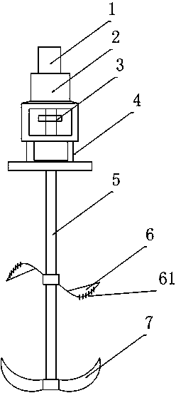
[0022] like figure 1 Shown, a kind of toilet soap mixing device comprises the motor 1 that is arranged on the top, the speed reducer 2 that is arranged on the bottom of motor 1, the frame that is arranged on the bottom of speed reducer 2, the shaft coupling 31 that is arranged on the inside of the frame, set The sealing element 4 at the lower part of the frame, the stirring shaft 5 is arranged under the sealing element 4, the stirring shaft 5 is connected with the coupling 31, the coupling 31 is connected with the motor 1, and the middle part of the stirring shaft 5 is provided with The upper stirring blade 6 and the lower stirring blade 7 are arranged on the lower part of the stirring shaft 5, and the upper stirring blade 6 and the lower stirring blade 7 are both sleeved on the stirring shaft 5, the upper stirring blade 6 is S-shaped, and the two ends of the S-shaped A willow-shaped sheet is provided, and the lower stirring blade 7 is crescent-shaped.

[0023] In the traditi...

Embodiment 2

[0025] Similar to Embodiment 1, the distinguishing feature is that the upper stirring blade 6 includes a left half leaf and a right half leaf, and the left half leaf and the right half leaf are both movably arranged on the stirring shaft 5 with the stirring shaft 5 as the center. Rotate up and down in the vertical plane. Being divided into two parts makes it easy to replace the upper stirring blade 6 and contributes to prolonging the service life of the entire stirring device.

[0026] A plurality of rings 61 are arranged on the edge of the sheet, and the intervals between the plurality of rings 61 are equal. The setting of the ring 61 can further stir the liquid level, so that the liquid is mixed more fully and the effect is more obvious.

[0027] The sizes of the multiple rings 61 are arranged from small to large from the stirring shaft 5 to the two ends of the upper stirring blade 6 . The larger rings 61 arranged at both ends of the upper stirring blade 6 can push a large...


PUM


Abstract

The invention discloses a soap stirring device. The device comprises a motor which is arranged at the uppermost part, a speed reducer which is arranged at the lower part of the motor, a frame which is arranged at the lower part of the speed reducer, a coupler which is arranged inside the frame and a sealing part which is arranged on the lower part of the frame, wherein a stirring shaft is arranged below the sealing part. According to the device disclosed by the invention, total reaction liquid can be fully reacted and meanwhile, the reaction speed can be further improved, the production time is shortened and the unit product efficiency is improved.

Description

[0001] technical field [0002] The invention relates to the field of machinery, in particular to a soap stirring device. Background technique [0003] The process of making soap or soap is generally produced by liquid phase heating, stirring and mixing. After the raw materials are added, a stirring device is required for stirring processing. [0004] Existing stirring device is to adopt the stirring bar with concave both sides high, and the stirring device is a stirring process of the toilet soap reaction liquid or soap production reaction liquid housed in it from the bottom of the stirring container upwards, and the degree of stirring at the bottom is obviously higher than that of The stirring degree of the upper part, the mixing of the soap reaction liquid or the soap reaction liquid is insufficient, the dispersion of the active ingredients of the obtained soap or soap in the whole soap body is not very uniform, and the detergency of the soap or soap is not very high. ...

Claims


Application Information

Patent Timeline
Patent Type & Authority Applications(China)
IPC IPC(8): C11D13/10B01F7/00
Inventor 张兴寿
Owner 绵阳原香农业科技有限公司
Learn More