
Zero-incisure cervical fusion cage with self-stabilization ridges

An intervertebral cage and cage technology, which can be applied to spinal implants and other directions, can solve the problems of interfering with bone growth in the air of bone grafting, unfavorable osteogenesis, endplate cutting implants, etc., saving operation time and economic costs, The effect of avoiding local load concentration, good immediate stability

Inactive Publication Date: 2015-02-04
WEST CHINA HOSPITAL SICHUAN UNIV
View PDF6 Cites 3 Cited by
  • Summary
  • Abstract
  • Description
  • Claims
  • Application Information

AI Technical Summary

Problems solved by technology

In order to achieve immediate postoperative stability, after implantation of the zero-profile intervertebral fusion cages currently on the market, 2 to 4 screws or two inserts need to be screwed obliquely at the tail to fix the fusion cages on the upper and lower vertebrae. The operation time is cumbersome, the operation time is prolonged, and the cost is also high; the concentrated load around the implanted screw or insert causes stress shielding, which is not conducive to bone formation; the oblique fixation of the screw or insert is prone to endplate cutting and causes internal damage. The plant is loose; screws or inserts are mostly made of titanium alloy materials, which are opaque to X-rays, and the artifacts are relatively large during MRI or CT examinations, which interferes with the observation of bone graft growth in the air

Method used


Image

  • Zero-incisure cervical fusion cage with self-stabilization ridges
  • Zero-incisure cervical fusion cage with self-stabilization ridges
  • Zero-incisure cervical fusion cage with self-stabilization ridges

Examples


Embodiment Construction

[0020] The present invention will be further described below in conjunction with the accompanying drawings.

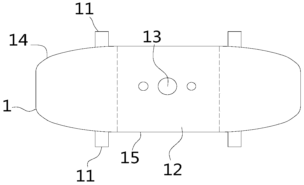
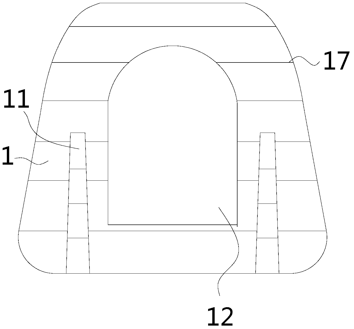
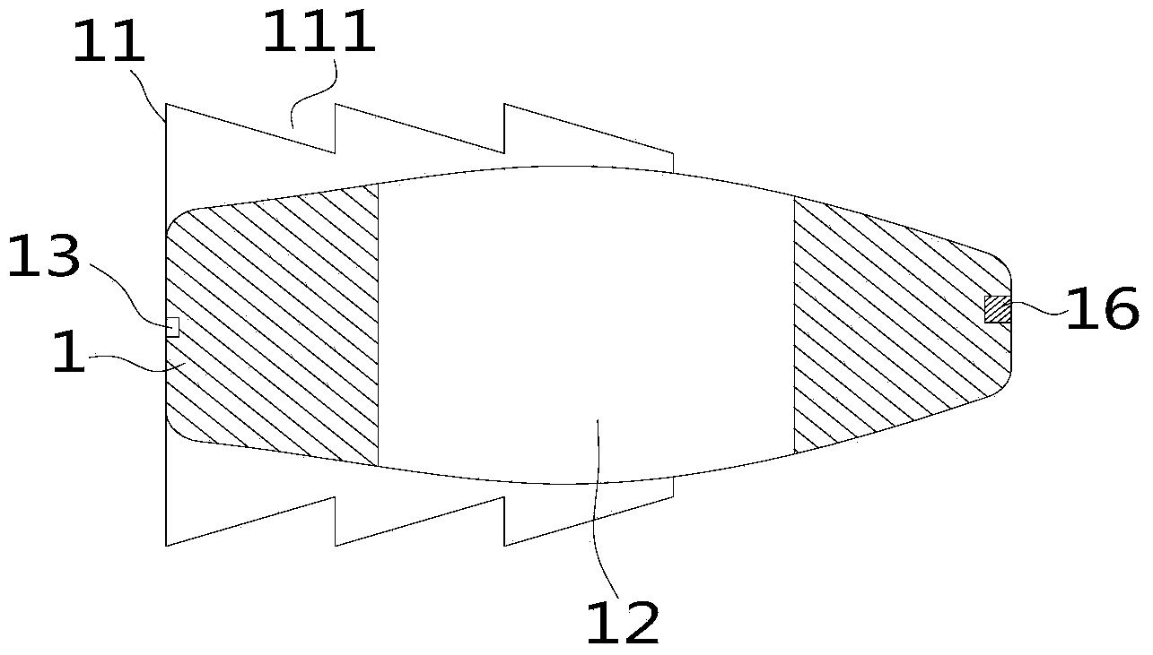
[0021] Such as figure 1 , figure 2 , image 3 , Figure 4 The shown zero-profile cervical intervertebral fusion device with a self-stabilizing ridge includes a fusion device body 1, a bone graft channel 12 arranged vertically in the fusion device body 1, and the upper surface of the fusion device body 1 14 and the lower surface 15 are symmetrically provided with a pair of self-stabilizing ridges 11 , the central axes of the self-stabilizing ridges 11 are parallel to each other and the top surfaces of the self-stabilizing ridges 11 are provided with anti-backover teeth 111 .

[0022] As the key of the present invention, the self-stabilizing ridge 11 not only plays a role of fixation, but also realizes a more uniform load transmission, avoids local load concentration, and is more conducive to bone growth. Generally, the pairs of self-stabilizing ridges 11 on the upp...


PUM


Abstract

The invention relates to the field of medical apparatus and instruments for cervical vertebra, in particular to a zero-incisure cervical fusion cage with self-stabilization ridges; the technical problem to be solved by the invention is to provide the zero-incisure cervical fusion cage with the self-stabilization ridges, which not only can be immediately stabilized but also is fixed without screwing a screw or an insertion plate into the tail part of the cervical fusion cage. The zero-incisure cervical fusion cage with the self-stabilization ridges comprises a fusion cage body and a bone grafting straight slot formed in the fusion cage body along the vertical direction; the upper surface and the lower surface of the fusion cage body are respectively and symmetrically provided with the paired self-stabilization ridges; the central axes of the self-stabilization ridges are parallel with each other, and the top face of each self-stabilization ridge is provided with anti-back pawls. The concept of the zero-incisure cervical fusion cage with the self-stabilization ridges, disclosed by the invention, has the skillful points that not only can the transmission of vertebra load be more uniform to avoid local load concentration but also clinical operation is very convenient, and the pain of patients is relieved by creatively utilizing the self-stabilization ridges; the zero-incisure cervical fusion cage has a very promotion prospect, and is especially suitable for anterior decompression and fusion operative treatment on cervical spondylosis.

Description

technical field [0001] The invention relates to the field of cervical spine medical devices, in particular to a zero-profile cervical intervertebral fusion device with a self-stabilizing ridge. Background technique [0002] Anterior cervical discectomy, decompression and bone graft fusion is a classic surgical method for the treatment of cervical spondylosis. The use of intervertebral fusion device reduces the incidence of non-fusion of bone graft and pseudarthrosis, and the zero-profile intervertebral fusion device does not require anterior titanium plate Auxiliary fixation reduces postoperative dysphagia. In order to achieve immediate postoperative stability, after implantation of the zero-profile intervertebral fusion cages currently on the market, 2 to 4 screws or two inserts need to be screwed obliquely at the tail to fix the fusion cages on the upper and lower vertebrae. The operation time is cumbersome, the operation time is prolonged, and the cost is also high; the ...

Claims


Application Information

Patent Timeline
IPC IPC(8): A61F2/44
Inventor 刘浩孟阳洪瑛王贝宇
Owner WEST CHINA HOSPITAL SICHUAN UNIV
Learn More