
Dual-frequency circularly polarized antenna device for uhf-band satellite communication

A circularly polarized antenna, satellite communication technology, applied in the antenna grounding device, antenna, radiating element structure and other directions, can solve the problems of large antenna design size, unsatisfactory use environment with limited height, and high four-armed helical antenna, Achieve the effect of correcting the center frequency drift of the antenna, easy to integrate and use, and enhance the diffraction effect

Inactive Publication Date: 2017-01-18
PLA UNIV OF SCI & TECH
View PDF5 Cites 0 Cited by
  • Summary
  • Abstract
  • Description
  • Claims
  • Application Information

AI Technical Summary

Problems solved by technology

[0003] For antenna devices with a working frequency range of 300MHz~400MHz, this frequency band belongs to the low frequency band of the UHF band, and the antenna design size is relatively large. If a common microstrip antenna is used, in order to meet the bandwidth and work dual-band requirements, more microwave medium, which not only greatly increases the weight of the antenna, but also reduces the efficiency of the antenna
In addition, the quadrifilar helical antenna is a wide-beam antenna, and its half-power beamwidth can usually reach 150°, but the quadrifilar helical antenna is relatively high. In order to achieve a wider beamwidth, the antenna height exceeds 0.8λ (λ is the working of the antenna wavelength), does not meet the highly restricted use environment, and this antenna has a complex structure and is not easy to produce

Method used


Image

  • Dual-frequency circularly polarized antenna device for uhf-band satellite communication
  • Dual-frequency circularly polarized antenna device for uhf-band satellite communication
  • Dual-frequency circularly polarized antenna device for uhf-band satellite communication

Examples


Embodiment Construction

[0024] The present invention will be further described below in conjunction with specific drawings and embodiments.

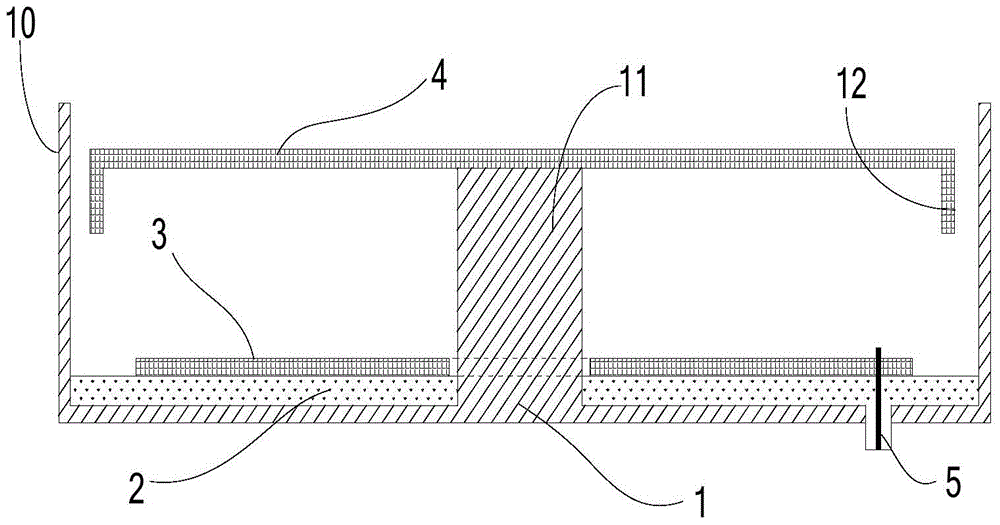
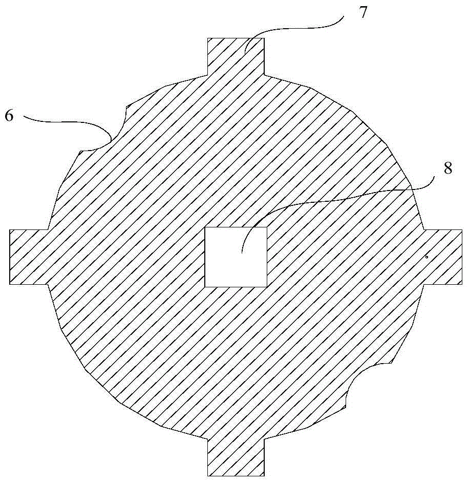
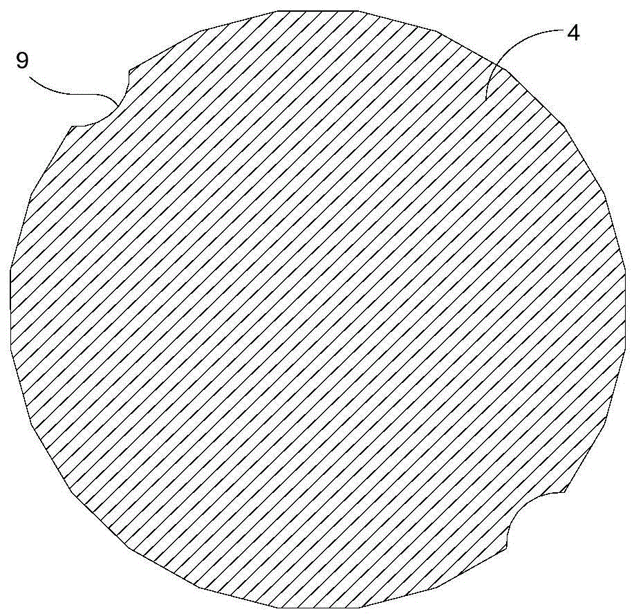
[0025] Such as figure 1 As shown: In order to effectively reduce the size of the antenna, widen the beam width of the antenna, reduce weight and cost, and facilitate production, the present invention includes a reflection cavity, which includes the antenna floor 1 and is distributed vertically upward on the edge of the antenna floor 1 The floor electric field coupling plate 10 on the top of the reflection cavity is provided with a microwave dielectric plate 2 matching the shape of the reflection cavity. The microwave dielectric plate 2 is located at the bottom of the reflection cavity and is fixedly connected to the antenna floor 1. On the microwave dielectric plate 2 An excitation patch 3 is provided, and a parasitic patch 4 is arranged directly above the excitation patch 3, and the parasitic patch 4 is fixed on the top of the patch support column 11, and the ...


PUM


Abstract

The invention relates to a UHF waveband satellite communication dual-band circularly polarized antenna device which comprises a reflection cavity. The reflection cavity comprises an antenna floor and floor electric field coupling plates. A microwave dielectric slab is arranged in the reflection cavity, an excitation patch is arranged on the microwave dielectric slab, and a parasitic patch is arranged over the excitation patch. The edge of the parasitic patch is provided with vertically-downward patch electric field coupling plates, and the patch electric field coupling plates are parallel to the floor electric field coupling plates. Gaps exist between the patch electric field coupling plates and the floor electric field coupling plates, and the patch electric field coupling plates and the floor electric field coupling plates are coupled in a staggered mode in the vertical direction. The UHF waveband satellite communication dual-band circularly polarized antenna device is compact in structure, the size of an antenna can be effectively decreased, the wave beam width of the antenna is increased, the weight is low, production is easy, the cost is low, the application range is wide, and safety and reliability are achieved.

Description

technical field [0001] The invention relates to an antenna device, in particular to a UHF band satellite communication dual-frequency circularly polarized antenna device, which belongs to the technical field of antenna design. Background technique [0002] In UHF band satellite communication applications, mobile communication terminal antennas are usually required to have wide beam, dual-band, and circular polarization performance characteristics to meet communication requirements, and as the development of mobile terminals tends to be miniaturized, so more requirements are put forward for the antenna size. How to design an antenna device with small size, light weight and compact structure is also the focus of satellite communication antenna design. [0003] For antenna devices with a working frequency range of 300MHz~400MHz, this frequency band belongs to the low frequency band of the UHF band, and the antenna design size is relatively large. If a common microstrip antenna ...

Claims


Application Information

Patent Timeline
Patent Type & Authority Patents(China)
IPC IPC(8): H01Q1/36H01Q1/38H01Q1/48H01Q19/10
Inventor 余同彬李洪彬项阳
Owner PLA UNIV OF SCI & TECH
Learn More