
Gate drive circuit capable of enhancing circuit drive ability

A gate drive circuit and circuit drive technology, which is applied in the direction of instruments, static indicators, etc., can solve the problems of unfavorable narrow frame design trend of gate drive circuit, large layout space, and insufficient stability of low potential of output signal, etc.

Inactive Publication Date: 2015-01-28
AU OPTRONICS CORP
View PDF0 Cites 25 Cited by
  • Summary
  • Abstract
  • Description
  • Claims
  • Application Information

AI Technical Summary

Problems solved by technology

However, when the above-mentioned voltage stabilizing module generates a high-potential node voltage through the capacitive coupling effect, it will also be affected by parasitic capacitors, which makes the low-potential of the output signal of the current stage not stable enough.
To increase the stability of the circuit, it is necessary to use a large-sized coupling capacitor to maintain the high potential of the above nodes, but large capacitors will occupy a large layout space, making the gate drive circuit unfavorable to the design trend of narrow borders

Method used


Image

  • Gate drive circuit capable of enhancing circuit drive ability
  • Gate drive circuit capable of enhancing circuit drive ability
  • Gate drive circuit capable of enhancing circuit drive ability

Examples


Embodiment Construction

[0045] In order to make the technical content disclosed in this application more detailed and complete, reference may be made to the drawings and the following various specific embodiments of the present invention, and the same symbols in the drawings represent the same or similar components. However, those skilled in the art should understand that the examples provided below are not intended to limit the scope of the present invention. In addition, the drawings are only for schematic illustration and are not drawn according to their original scale.

[0046] The specific implementation manners of various aspects of the present invention will be further described in detail below with reference to the accompanying drawings.

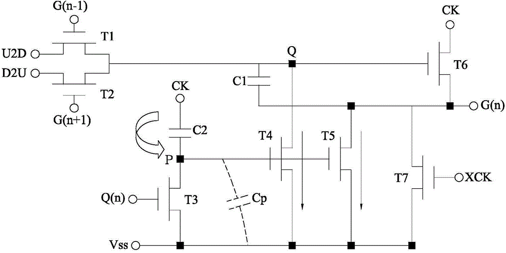
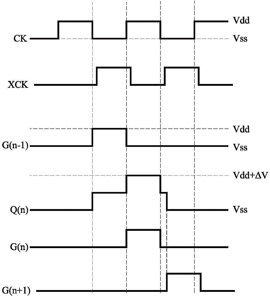
[0047] figure 1 A schematic structural diagram of a gate driving circuit in the prior art is shown. figure 2 show figure 1 Schematic diagram of the timing of key signals in the gate drive circuit.

[0048] refer to figure 1 , the gate drive circuit in...


PUM


Abstract

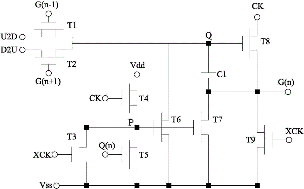
The invention provides a gate drive circuit capable of enhancing circuit drive ability. The gate drive circuit capable of enhancing the circuit drive ability comprises nine transistors from a first one to a ninth one, wherein a control end of the first transistor is connected with an n-1th level gate drive signal, a second end of the first transistor is electrically connected with first control voltage, a control end of the second transistor is connected with an n+1th level gate drive signal, a first end of the second transistor is connected with second control voltage, a control end of the third transistor is connected with a first clock pulse signal, a second end of the third transistor is connected with a first direct current source, a control end of the forth transistor is connected with a second clock pulse signal, and a first end of the forth transistor is coupled with a second direct current source. Compared with the prior art, the forth transistor is arranged on the gate drive circuit capable of enhancing the circuit drive ability so as to avoid voltage reduction caused by stray capacitance, and furthermore the second direct current source can restrain leakage currents in the transistors, and duration of high potential of nodes is prolonged. Accordingly, large capacitance in the gate drive circuit capable of enhancing the circuit drive ability can be omitted, and the size of a board arrangement space occupied by the gate drive circuit capable of enhancing the circuit drive ability is reduced.

Description

technical field [0001] The invention relates to a gate drive circuit, in particular to a gate drive circuit capable of enhancing the drive capability of the circuit. Background technique [0002] In a thin film transistor liquid crystal display (Thin Film Transistor Liquid Crystal Display, TFT-LCD), each pixel has a thin film transistor (Thin Film Transistor, TFT), the gate of the thin film transistor is electrically connected to the scanning line in the horizontal direction, The drain is electrically connected to the vertical data line, and the source is electrically connected to a pixel electrode. If a sufficient positive voltage is applied to a scanning line in the horizontal direction, all the TFTs on the scanning line will be turned on, and at this time, the pixel electrode corresponding to the scanning line will be connected to the data line in the vertical direction, thereby connecting the data line The video signal voltage is written into the pixels, and then the tr...

Claims


Application Information

Patent Timeline
IPC IPC(8): G09G3/36
Inventor 林志隆吴佳恩陈福星塗俊达
Owner AU OPTRONICS CORP
Learn More