Conveyer belt troughability test method and apparatus
A technology of test device and conveyor belt, which is applied in the direction of measuring device, test of mechanical parts, test of machine/structural parts, etc., and can solve the problem that the test result deviates from the actual value, etc.
- Summary
- Abstract
- Description
- Claims
- Application Information
AI Technical Summary
Problems solved by technology
Method used
Image
Examples
Embodiment 1
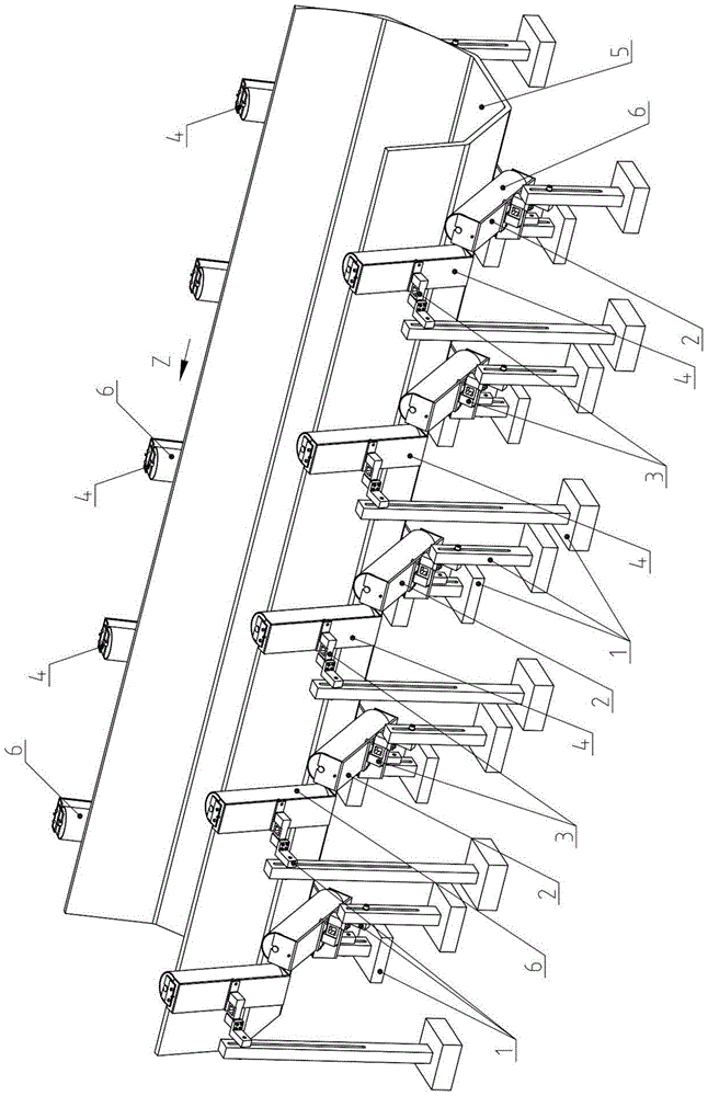
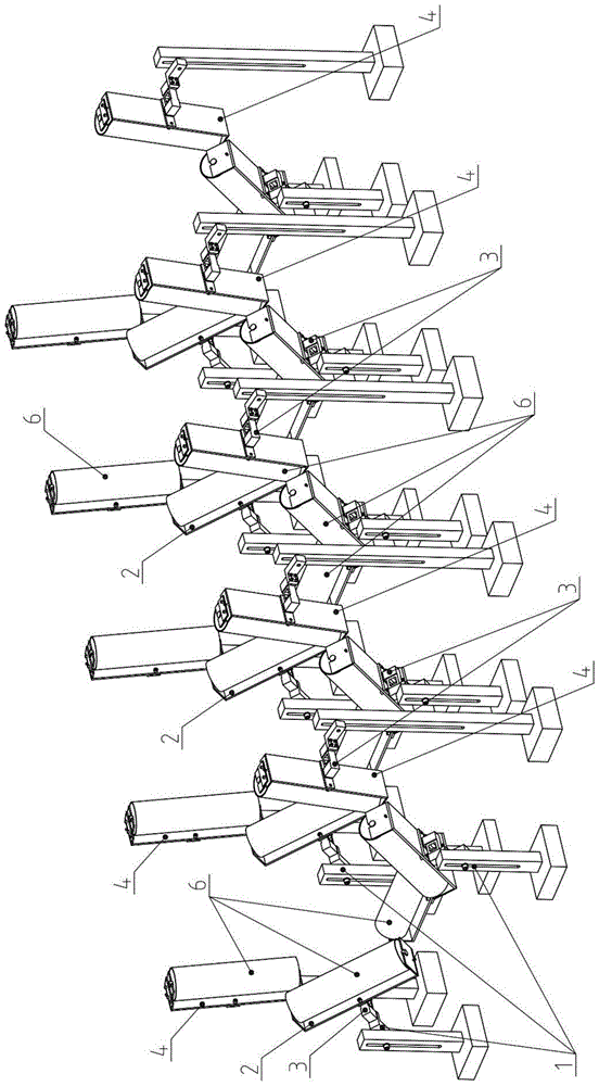
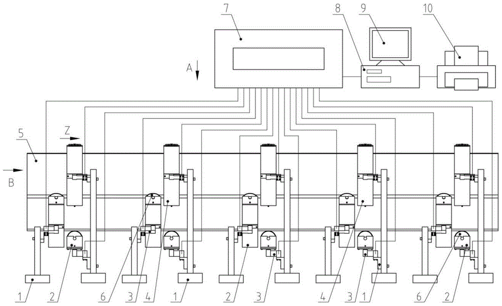
[0073] Embodiment 1: see Figure 1 to Figure 9 and Figure 24 .
[0074] A conveyor belt troughability test device, including 5 sets of trough idler rollers arranged along the direction Z of the conveyor belt sample 5, each trough idler set includes 5 idler rollers 6, two of which are side supports rollers, the rest are intermediate rollers, the size and position of the troughed rollers are exactly the same as those on the corresponding troughed belt conveyors, by image 3 and Figure 4 It can be seen that the axis line of each idler 6 is perpendicular to the direction Z of the conveyor belt sample 5, can translate along the direction Z of the conveyor belt sample 5, and can translate and rotate in a section perpendicular to the direction. The rollers are set in such a way that they can be flexibly adjusted and replaced, so as to adapt to various specifications and models of trough roller sets and conveyor belt samples 5; The idler seat 2 or the forward-inclining roller se...
Embodiment 2
[0087] Embodiment 2: A kind of conveyor belt troughability test method and device, see Figure 9 to Figure 19 .
[0088] The combination of one group of mechanical arms and the lifting mechanism is installed on a large carriage assembly 14, and the large carriage assembly 14 is connected with the base assembly 12 through a moving pair. The moving pair is a linear guide rail pair, a slide block 14-1 is installed on the large carriage assembly 14, and a linear guide rail 12-1 is installed on the base assembly 12, and the two form a linear guide rail pair.
[0089] For the combination of multiple groups of mechanical arms and lifting mechanisms described above, three groups are provided in this embodiment.
[0090] The combination of each group of mechanical arms and lifting mechanism described above includes 2 large mechanical arms 15, 2 small mechanical arms 17 and a lifting mechanism 13. The lifting mechanism 13 is installed in the middle of the large pallet assembly 14 by sc...
Embodiment 3
[0109] Embodiment 3: A kind of conveyer belt grooving test device, see Figure 20 to Figure 21 .
[0110] The specification of the idler 6 used in this embodiment is φ89x200 mm, and the width of the tested conveyor belt sample 5 is 650 mm. Each trough-shaped idler group includes 4 idlers 6, and the axes of the two side idlers 6 On a plane, the angle between the horizontal plane and the horizontal plane is 60°, installed on two large mechanical arms 15, the axis lines of the two middle rollers 6 are on the same plane, and the axis line is 25° from the horizontal plane, Be installed on two small mechanical arms 17. The elevating mechanism 13 is not idle, and the handwheel 13-8 is rotated so that the elevating frame 13-1 is in a relatively low position, so that other mechanisms can not be hindered from working.
[0111] Other structures, functions and operation methods are the same as in Embodiment 2.
PUM
 Abstract
Description
Claims
Application Information
 - Generate Ideas
- Intellectual Property
- Life Sciences
- Materials
- Tech Scout
- Unparalleled Data Quality
- Higher Quality Content
- 60% Fewer Hallucinations
Browse by: Latest US Patents, China's latest patents, Technical Efficacy Thesaurus, Application Domain, Technology Topic, Popular Technical Reports.
© 2025 PatSnap. All rights reserved.Legal|Privacy policy|Modern Slavery Act Transparency Statement|Sitemap|About US| Contact US: help@patsnap.com


