Shaft and method used for reducing heat loss

A heat loss and wellbore technology, which is applied in the field of oil field steam injection technology and oil production technology, can solve the problems of ineffective displacement of crude oil, increase in water content, reduce steam heat utilization rate, etc. degree of effect

Active Publication Date: 2015-01-28
PETROCHINA CO LTD
View PDF8 Cites 0 Cited by
  • Summary
  • Abstract
  • Description
  • Claims
  • Application Information

AI Technical Summary

Problems solved by technology

Steam injection from high-temperature objects will inevitably transfer heat to the formation of low-temperature objects, and the heat of the steam injection steam will be lost. As a result, on the one hand, the dryness of the steam injected into the wellbore will decrease, and the water content in the wet steam will increase, resulting in a decrease in the energy carried by the steam reaching the bottom of the well. , cannot effectively displace crude oil, thereby reducing the heat utilization rate of steam. On the other hand, with the increase of the number and time of steam injection, the casing will be damaged due to long-term high temperature and high pressure.

Method used


Image

  • Shaft and method used for reducing heat loss
  • Shaft and method used for reducing heat loss

Examples


Embodiment Construction

[0024] The details of the present invention can be understood more clearly with reference to the accompanying drawings and the description of specific embodiments of the present invention. However, the specific embodiments of the present invention described here are only for the purpose of explaining the present invention, and should not be construed as limiting the present invention in any way. Under the teaching of the present invention, the skilled person can conceive any possible modification based on the present invention, and these should be regarded as belonging to the scope of the present invention.

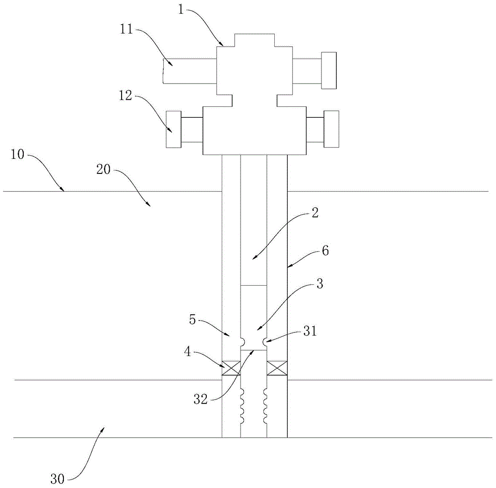
[0025] refer to figure 1 As shown, the present invention discloses a wellbore for reducing heat loss, which includes a casing 6 and an oil pipe 2 pierced in the casing 6, and the casing 6 and the oil pipe 2 enter from the ground 10 The formation 20 extends from the formation 20 into the oil layer 30. An annular space 5 is formed between the casing 6 and the tubing 2. The...


PUM


Abstract

The invention discloses a shaft used for reducing heat loss. The shaft comprises a casing pipe and an oil pipe penetrating through the casing pipe, wherein the casing pipe and the oil pipe go into an oil layer from the ground. The shaft is characterized in that an annular space is formed between the casing pipe and the oil pipe; the shaft also comprises a well mouth component arranged above the ground and provided with a first flowing passage and a second flowing passage; the first flowing passage is communicated with the oil pipe; the second flowing passage is communicated with the annular space; the first flowing passage is separated from the second flowing passage; the shaft also comprises a packer and a steam-water separation device; the packer is arranged above the oil layer and is positioned in the annular space; the steam-water separation device is arranged above the packer and is provided with a first separation opening and a second separation opening; the first separation opening is used for separating saturated water out and is communicated with the annular space; the second separation opening is used for separating dry steam out and is communicated with the oil layer. Due to the fact that the method and the structure are adopted, and the heat loss of the shaft is counteracted by the energy of the saturated water, the energy of the steam in the shaft is protected, and the steam filling quality and the dryness of the steam at the bottom of the shaft are improved.

Description

technical field [0001] The invention belongs to an oil field steam injection technology and an oil recovery technology, in particular to a wellbore and a method for reducing heat loss. Background technique [0002] In the process of thermal extraction of heavy oil, there is a common problem of heat loss in the wellbore. This is because the steam injection steam is wet saturated steam with a certain amount of energy. The dryness of the steam injection steam reaches the wellhead is generally about 70%, and the temperature is about 350 °C. The formation temperature is generally around 100°C. Steam injection from high-temperature objects will inevitably transfer heat to the formation of low-temperature objects, and the heat of the steam injection steam will be lost. As a result, on the one hand, the dryness of the steam injected into the wellbore will decrease, and the water content in the wet steam will increase, resulting in a decrease in the energy carried by the steam reachi...

Claims


Application Information

Patent Timeline
Patent Type & Authority Applications(China)
IPC IPC(8): E21B43/24
CPCE21B36/00E21B43/24
Inventor 张红朋许宝燕马庆李娟娟张曦宇由春坤陈楠邵恒玉
Owner PETROCHINA CO LTD
Why Eureka
Try Eureka