
Unloading system for bars and sections

A bar and section steel technology, which is applied in the field of steel loading system, can solve the problems of high equipment cost, easy to overturn, low utilization rate of cooling bed, etc., and achieve the effect of reducing equipment cost, stable transfer process, and improving steel loading efficiency

Active Publication Date: 2016-03-02
HUATIAN NANJING ENG & TECH CORP MCC
View PDF5 Cites 0 Cited by
  • Summary
  • Abstract
  • Description
  • Claims
  • Application Information

AI Technical Summary

Problems solved by technology

[0003] Since the rolled piece is divided into bar and section steel, and the opening angles of all the depressions on the moving and static racks on the existing bar cooling bed are exactly the same, when the section steel is cooled and deformed greatly, the inclination angle of some section steel is too large. The stepping transfer process is unstable and prone to overturning, so it is not suitable for the work of lowering steel
Most factories produce both bars and section steel, and the specifications of each rolled piece are various. In actual production, both section steel cooling bed and bar cooling bed are needed, resulting in high equipment cost, but in fact each The utilization rate of the cooling bed is low

Method used


Image

  • Unloading system for bars and sections
  • Unloading system for bars and sections
  • Unloading system for bars and sections

Examples


Embodiment 1

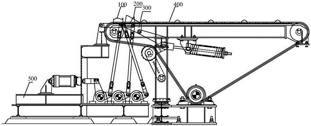
[0042] The steel lowering system applicable to bars and shaped steels in this embodiment includes a stepping lowered steel device, an auxiliary lowered steel device and a conveying device for transporting the bars or shaped steels. With the assistance of the auxiliary lowering device, the stepping lowering device can lower steel for both profiled steel and bars.

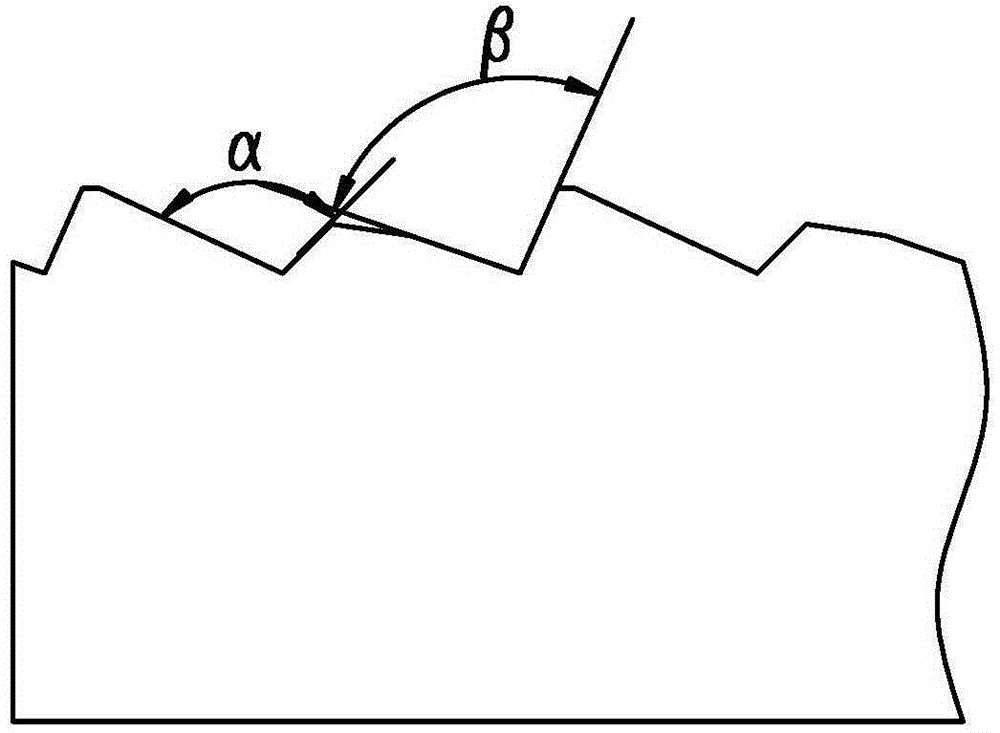
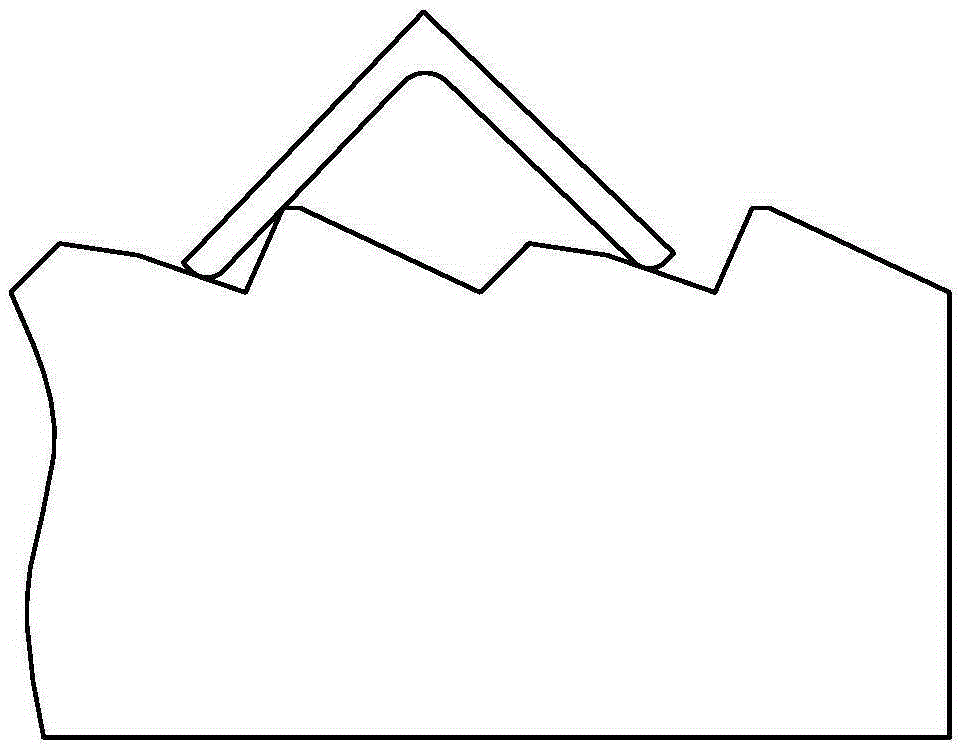
[0043] The stepping steel lowering device includes a movable rack, a static rack and a rack driving device for driving the movable rack to move steppingly. The movable rack and the static rack have the same tooth profile, and both are provided with a number of recesses for placing rods or profiles. The tooth shape of the movable rack in this embodiment is different from that in the prior art, and the opening angles of any two adjacent recesses on the movable rack in this embodiment are different. This setting is for the stability of the moving process and no overturning during the process of transferring the profile...

Embodiment 2

[0059] In this embodiment, on the basis of the above-mentioned embodiments, a bar grouping steel lowering device is provided, and the bar material grouping steel lowering device is set between the auxiliary steel lowering device and the conveying device, and is used for specifications smaller than The bars are grouped under steel. The steel bar grouping device includes a stop device and a sliding device.

[0060] The stop device 200 includes a stop baffle 206, a second driving device 201 and a second transmission device connected to the power output end of the second drive device, and the second drive device controls the stop device through the second transmission device. The movable baffle is in high or low position.

[0061] The second transmission device includes a third connecting rod 202, a second transmission shaft 203, a fourth connecting rod 204, a second screw rod 205, and a flat head. The third connecting rod 202 and the fourth connecting rod 204 are arranged on t...

Embodiment 3

[0077] In this embodiment, on the basis of the above-mentioned embodiment 1, five conveyor chain stoppers 409 are arranged on the conveyor chain, and these five conveyor chain stoppers divide the conveyor chain into four lower steel areas, and each two lower steel areas are One group is divided into two groups to realize the simultaneous conveying of two groups of rolled pieces. In this embodiment, the conveying chain is divided into regions using chain stoppers, so that the number of rolling pieces in each region is relatively reduced, and the two ends of each region are controlled by chain stoppers, so the arrangement of the rolling pieces is more neat and orderly . In the follow-up work, the processes of straightening the section steel in rows and cold shearing and sectioning of the bar are smoother, which improves the work efficiency.


PUM

PropertyMeasurementUnit
angleaaaaaaaaaa
angleaaaaaaaaaa
angleaaaaaaaaaa

Abstract

The invention discloses a steel unloading system suitable for bars and section steel, and mainly aims to solve the problem that steel unloading of bars and section steel cannot be implemented simultaneously in the prior art. The steel unloading system comprises a stepping steel unloading device, an auxiliary steel unloading device and a conveying device, wherein the stepping steel unloading device comprises a movable rack, a static rack and a rack driving device; the auxiliary steel unloading device comprises an auxiliary steel unloading baffle plate, a first driving device and a first transmission device; the first driving device is used for controlling the auxiliary steel unloading baffle plate to be positioned at a higher position or a lower position through the first transmission device; the conveying device comprises a conveying chain and a chain driving device. The shapes of recesses of the movable and static racks are improved, so that the section steel is conveyed more stably without being overturned. Therefore, the steel unloading system can be suitable for steel unloading of the bars and the section steel.

Description

technical field [0001] The invention relates to a steel lowering system suitable for bars and shaped steel. Background technique [0002] The cooling bed is an important process equipment in the steel rolling process, which is used for cooling and unloading of the rolled piece. [0003] Since the rolled piece is divided into bar and section steel, and the opening angles of all the depressions on the moving and static racks on the existing bar cooling bed are exactly the same, when the section steel is cooled and deformed greatly, the inclination angle of some section steel is too large. The stepping transfer process is unstable and prone to overturning, so it is not suitable for the work of lowering steel. Most factories produce both bars and section steel, and the specifications of each rolled piece are various. In actual production, both section steel cooling bed and bar cooling bed are needed, resulting in high equipment cost, but in fact each The utilization rate of th...

Claims


Application Information

Patent Timeline
Patent Type & Authority Patents(China)
IPC IPC(8): B65G25/02
Inventor 阮祥伟刘庆祖岳峰张少辉
Owner HUATIAN NANJING ENG & TECH CORP MCC
Learn More