
High-speed gearbox processing method

A processing method and gearbox technology, applied in the field of gearbox processing, can solve the problems of large coaxiality error of bearing holes on the gearbox, inaccurate positions of screw holes and positioning pin holes, etc., to ensure quality, ensure positioning accuracy, The effect of ensuring the degree of position

Active Publication Date: 2015-01-28
CHONGQING JIANGJIN SHIPBUILDING IND
View PDF8 Cites 14 Cited by
  • Summary
  • Abstract
  • Description
  • Claims
  • Application Information

AI Technical Summary

Problems solved by technology

[0009] In order to solve the problems in the prior art that the coaxiality of the bearing hole on the gearbox does not meet the requirements and lead to scrapping, the position of the connecting screw hole and the positioning pin hole on the gearbox is not accurate, and the position of the inclined hole on the gearbox is not accurate, the present invention provides a A high-speed gearbox processing method, the method cooperates with the processed end face of the back cover to process the bearing hole on the body and the back cover, the screw hole on the body and the back cover for cooperation, and the positioning on the body and the back cover during rough machining Pin hole, to solve the technical problems of large coaxiality error of the bearing hole on the gearbox and inaccurate position of the screw hole and positioning pin hole. Use the equipment-specific mandrel to coincide the center of the high-speed bearing hole of the gearbox with the center of rotation of the machine tool, then drill the oblique holes on the gearbox, and calculate the angle of the oblique holes that do not reach the center of the circle and the center of the high-speed bearing hole of the gearbox and the offset distance of the boring bar , to ensure the position accuracy of the inclined hole on the gearbox

Method used


Image

  • High-speed gearbox processing method
  • High-speed gearbox processing method
  • High-speed gearbox processing method

Examples


Embodiment Construction

[0061] The specific implementation manner of the present invention will be described in further detail below in conjunction with the accompanying drawings.

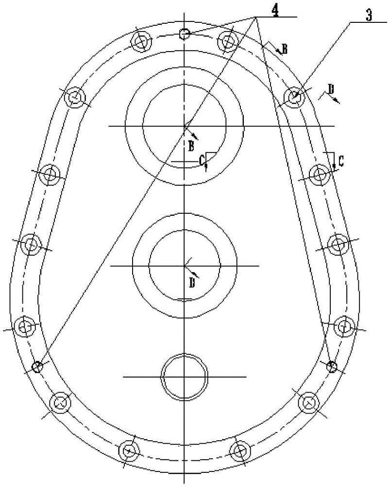
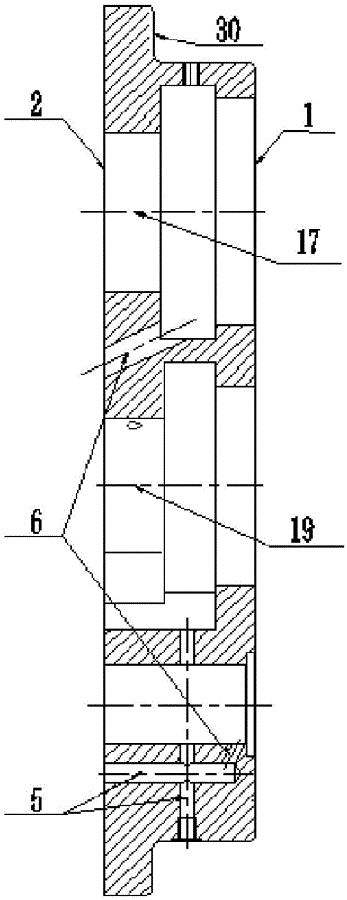
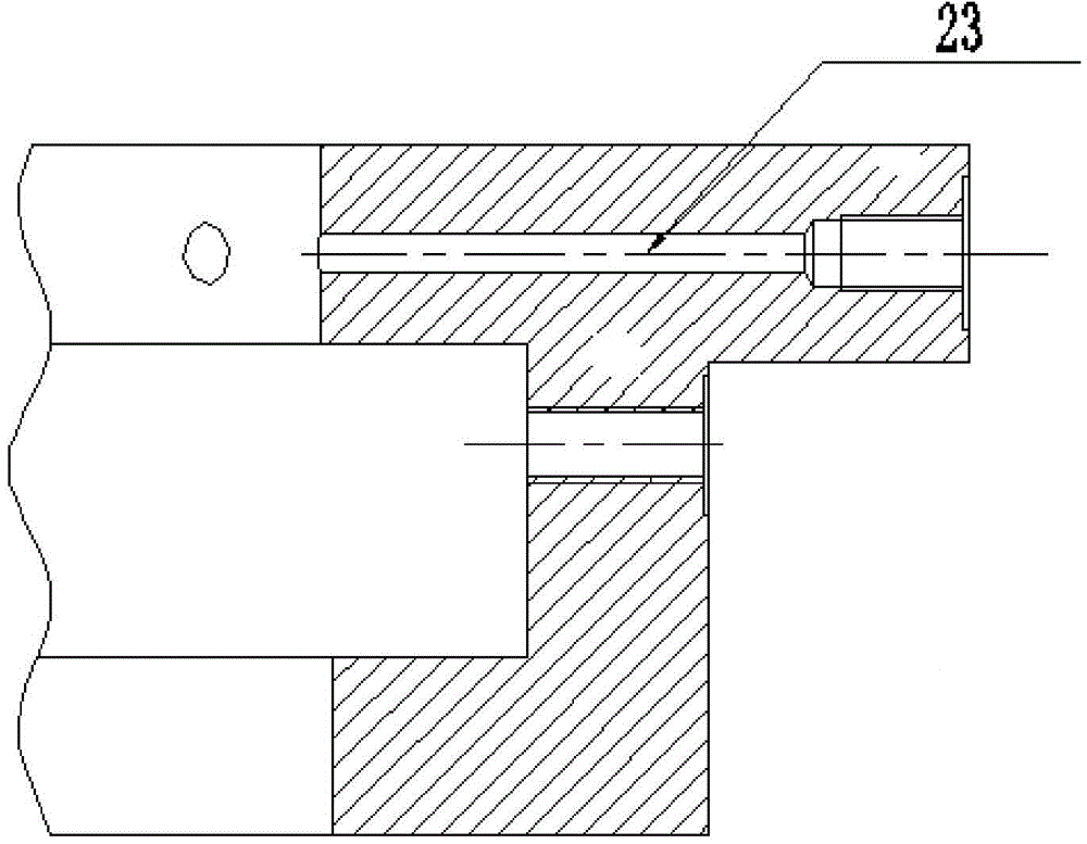
[0062] Such as Figure 1-12 Shown, a kind of high-speed gearbox processing method comprises the following steps:

[0063] a. Rough processing of the back cover:

[0064] a1. Remove the nodules and residual sand inside the blank of the back cover casting;

[0065] a2. Back cover castings are annealed to relieve stress;

[0066] a3. Based on the step surface 30 of the back cover, draw the starting processing line of the end face 1 of the back cover and the bonding surface 2 with the body, and the alignment lines of the bearing holes of all levels on the back cover;

[0067] a4. Roughly turn the end face of the rear cover according to the starting size and marking line 1;

[0068] a5. Laying surface 2 between the rough car turned over and the body;

[0069] a6. Drill the connection through hole 3, drill and tap the thre...


PUM


Abstract

The invention discloses a high-speed gearbox processing method, which is characterized in that when a body is roughly processed, a screw hole for matching a rear cover having roughly processed end faces in a processing body, coaxial bearing holes of the body and the rear cover, and a location pinhole for matching the body and the rear cover are adopted to guarantee the coaxiality of coaxial bearing holes of a gearbox and the position accuracy of the screw hole and the location pinhole; meanwhile after the end faces, various stages of bearing holes and gear pump holes are finely processed in gearbox combination processing, the high-speed bearing hole center of the gearbox and the rotation center of a machine tool are coincided by using a special spindle for equipment, then various inclined holes in the gearbox are drilled, a boring rod offset distance and an angle of the inclined hole shorter than the circle center offsetting the high-speed bearing hole center of the gearbox are calculated at the same time, and the position accuracy of the inclined holes in the gearbox is guaranteed.

Description

technical field [0001] The invention belongs to the technical field of gear box processing, and in particular relates to a high-speed gear box processing method. Background technique [0002] The gearbox parts are the basic parts of the high-speed gearbox. It connects the related parts into a whole, so that these parts can maintain the correct relative positional relationship and coordinate with each other. Therefore, the manufacturing accuracy of the gearbox will directly affect the assembly quality of the machine or components, and then affect the performance and life of the machine. Therefore, gearboxes generally have high technical requirements. The common characteristics of gearbox parts are: the blank is usually made of cast iron, the structure is complex, and the interior is cavity-shaped; there are several planes and hole systems with high precision requirements, and there are many fastening threaded holes, small diameter and deep oblique The holes are distributed ...

Claims


Application Information

Patent Timeline
Patent Type & Authority Applications(China)
IPC IPC(8): B23P15/00
CPCB23P15/00
Inventor 徐海燕段昌文柯益罗兵马宝栓
Owner CHONGQING JIANGJIN SHIPBUILDING IND
Learn More