A Debugging Method for Bonding of Annular Aspheric Mirror

A debugging method and aspheric technology, applied in the directions of instruments, installation, optics, etc., can solve the problems of poor consistency, difficult to effectively control the parallelism and coaxiality of annular aspherical mirrors, and achieve the effect of controlling coaxiality

Active Publication Date: 2020-07-28
LIUZHOU CHANGHONG MACHINE MFG
View PDF9 Cites 0 Cited by
  • Summary
  • Abstract
  • Description
  • Claims
  • Application Information

AI Technical Summary

Problems solved by technology

[0003] The purpose of the present invention is to provide a debugging method for the cementation of the annular aspheric reflector, which can effectively solve the problem that the parallelism and coaxiality between the annular aspheric reflector and the mirror base are difficult to be effectively controlled. The problem of poor consistency

Method used


Image

  • A Debugging Method for Bonding of Annular Aspheric Mirror
  • A Debugging Method for Bonding of Annular Aspheric Mirror
  • A Debugging Method for Bonding of Annular Aspheric Mirror

Examples


Embodiment Construction

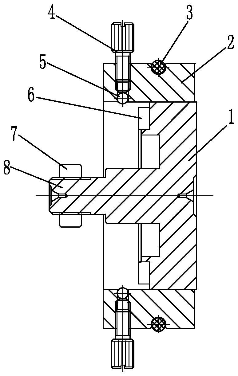
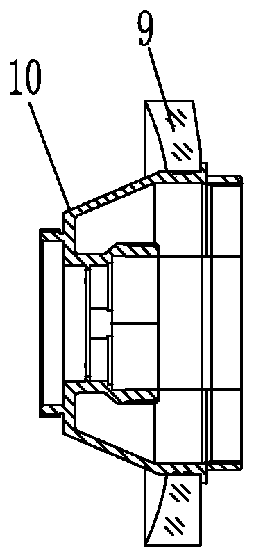
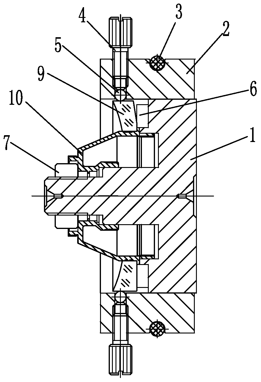
[0014] Such as Figure 1 to Figure 3 As shown, the debugging method of the cementation of a ring aspheric mirror in the present invention includes the following six steps.

[0015] (1) Set up the stereotyped adjustment tooling, which includes the base 1, the support ring 2, the washer 6, the clamping device and the fastening belt 3, and the positioning column 8 protruding from the center hole of the positioning mirror holder 10 in the middle of the base 1, and the positioning column The end of 8 is provided with an external thread, the support ring 2 is positioned outside the outer wall of the base 1, and the outer wall of the support ring 2 is evenly arranged with a plurality of through-holes on the same circumference. In this embodiment, a total of four through-holes are provided. The distance between the adjacent through holes is 90 degrees, the gasket 6 is placed on the inner surface of the base 1, and the tightening device is positioned in the through hole on the outer wa...


PUM


Abstract

The debugging method of the cementation of the annular aspheric reflector of the present invention relates to the debugging method of the reflector, comprising the following steps: (1) setting a stereotyped adjustment tool; Apply a layer of glue respectively, so that the mirror base and the annular aspheric mirror are initially bonded to form an annular aspheric mirror assembly; (3) Position the annular aspheric mirror assembly on the shaping adjustment tool; (4) Debug the annular The parallelism and coaxiality between the aspheric mirror and the mirror base; (5) Curing at room temperature; (6) Dismantling the shaping adjustment tooling outside the annular aspheric mirror assembly. The invention guarantees the parallelism and coaxiality of the annular aspheric reflector and the mirror base by the shaping adjustment tooling, and solves the problem that the parallelism between the annular aspheric reflector and the end surface of the mirror base increases due to the release of stress by the curing glue , effectively controlling the coaxiality of the annular aspheric mirror and the mirror base.

Description

technical field [0001] The invention relates to a debugging method for a reflecting mirror, in particular to a debugging method for cementing an annular aspheric reflecting mirror. Background technique [0002] In the past, the aspheric mirror bonding debugging method was to install the aspheric mirror on the mirror base, and the rear end surface of the aspheric mirror was close to the mirror base to ensure the parallelism between the aspheric mirror end surface and the mirror base end surface. The matching gap between the outer circle of the spherical mirror and the mirror seat and the thickness of the coating glue ensure the coaxiality of the aspheric mirror and the mirror seat. This approach has obvious shortcomings. The rear end surface of the aspheric mirror is close to the mirror seat. During the cementing process, it is easy to increase the parallelism between the end surface of the aspheric mirror and the end surface of the mirror seat due to the stress release duri...

Claims


Application Information

Patent Timeline
Patent Type & Authority Patents(China)
IPC IPC(8): G02B7/182
CPCG02B7/182
Inventor 覃海鲜
Owner LIUZHOU CHANGHONG MACHINE MFG
Why Eureka
Try Eureka