Springback compensation method of thin-wall stamped part with large relative bending radius
A relative bending radius and springback compensation technology, which is applied in the field of sheet metal processing, can solve problems such as high requirements for experience proficiency, difficult to estimate development costs, and unguaranteed development cycle, so as to achieve low experience requirements, shorten development cycle, eliminate The effect of theoretical rebound
- Summary
- Abstract
- Description
- Claims
- Application Information
AI Technical Summary
Problems solved by technology
Method used
Image
Examples
Embodiment 1
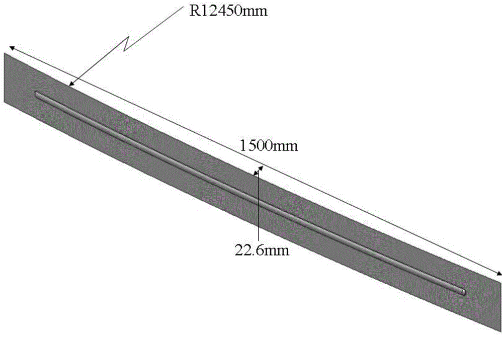
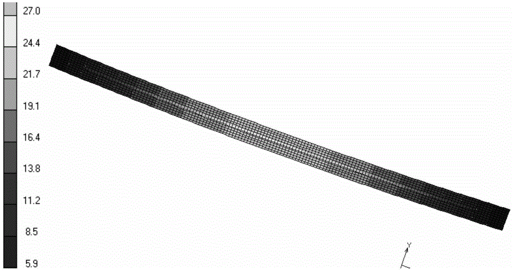
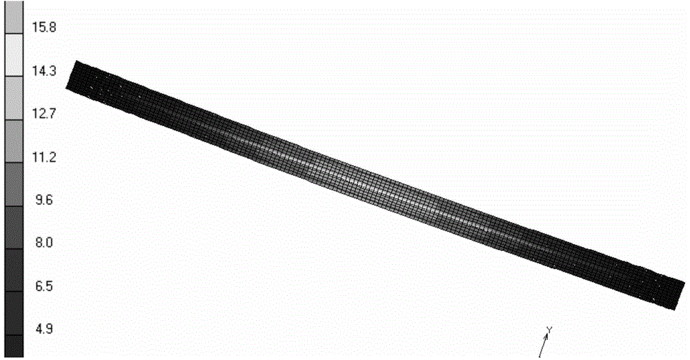
[0029] Large relative bending radius thin-walled stampings, such as figure 1 As shown, the material is 5052-O aluminum alloy, the wall thickness is 1.5mm, the bending radius is 12450mm, the chord length is 1500mm, the arch height is 22.6mm, the relative bending radius r / t is very large, and the dimensional accuracy of the parts requires the deviation of the arch height to be 3mm within. Using MSC.MARC 2005 finite element analysis software to analyze the springback of this stamping part, the results are as follows figure 2 with 3 shown. It can be seen from the figure that although the stamping parts use ribs to increase their rigidity, there is still a large springback after forming. The finite element analysis results show that the deviation has reached 10.1mm, which is seriously out of tolerance.
specific Embodiment approach
[0030] The specific embodiment is carried out according to the following process steps:
[0031] The first step, springback analysis of stamping parts: use MSC.MRAC finite element software to analyze the springback of thin-walled stamping parts with large relative bending radius, and obtain the data of the first mold (that is, the required size of the part) and the first springback after forming. bomb data, such as Figure 4 As shown, take the difference Aa as the first rebound compensation amount;
[0032] The second step, the first rebound compensation: as Figure 5 As shown, select a number of control points, and correct the mold so that the first modulus AB = Aa, and then use the finite element software to perform springback analysis to obtain the second springback, and compare the first mold and the second springback The difference Ab is used as the second rebound compensation amount;
[0033] The third step, the second springback compensation: On the basis of the seco...
Embodiment 2
[0036] On the basis of embodiment 1, the multi-point forming die is adopted, the finite element technique is combined with the multi-point forming technology, and after the third step of embodiment 1 is completed, the following steps are carried out:
[0037] 1) Import the forming surface: save the modified mold data obtained in the third step and theoretically meet the dimensional accuracy requirements in IGES format, and import it into the multi-point forming software to generate a 3D model; the multi-point forming software can directly identify Surface in IGES format;
[0038] 2) Check and generate the forming surface: Use the mouse or keyboard to rotate, translate or zoom the 3D model in real time to check and correct the surface of the 3D model. After the check is correct, the multi-point forming software automatically calculates and orders the multi-point forming mold to generate forming surface;
[0039] 3) Multi-point forming of slab: Place the slab of thin-walled sta...
PUM
 Abstract
Description
Claims
Application Information
 - R&D
- Intellectual Property
- Life Sciences
- Materials
- Tech Scout
- Unparalleled Data Quality
- Higher Quality Content
- 60% Fewer Hallucinations
Browse by: Latest US Patents, China's latest patents, Technical Efficacy Thesaurus, Application Domain, Technology Topic, Popular Technical Reports.
© 2025 PatSnap. All rights reserved.Legal|Privacy policy|Modern Slavery Act Transparency Statement|Sitemap|About US| Contact US: help@patsnap.com


