
Phased Array Beam Tracking Method

A technology of beam tracking and phased array, which is applied in radio wave measurement system, radio wave reflection/re-radiation, utilization of re-radiation, etc., can solve the problems of angle measurement and beam tracking of small annular common phased array, and achieve Conducive to miniaturized design, satisfying decoupling operation, and reducing complexity

Active Publication Date: 2017-07-14
SHANGHAI RADIO EQUIP RES INST
View PDF1 Cites 0 Cited by
  • Summary
  • Abstract
  • Description
  • Claims
  • Application Information

AI Technical Summary

Problems solved by technology

[0009] The invention provides a phased array beam tracking method, which solves the problem of angle measurement and beam tracking of a small annular common phased array without a sum and difference network

Method used


Image

  • Phased Array Beam Tracking Method
  • Phased Array Beam Tracking Method
  • Phased Array Beam Tracking Method

Examples


Embodiment Construction

[0041] Specific embodiments of the present invention will be further described below in conjunction with the accompanying drawings.

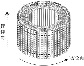
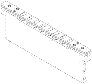
[0042] The invention discloses a phased array beam tracking method for a small annular common type phased array. The application and research background of the present invention is a small annular conformal phased array. The diameter of the small annular conformal phased array is less than 200 mm and the height is less than 170 mm. The annular conformal phased array is formed by splicing several one-dimensional linear arrays conformally in the azimuth direction. Due to its small size, phased arrays cannot be designed with sum and difference networks in azimuth. Therefore, the tracking of the beam in the azimuth direction cannot be realized by conventional monopulse angle measurement. The invention solves the problem of angle measurement and beam tracking of a small ring-shaped common phased array in the absence of a sum-difference network by u...


PUM


Abstract

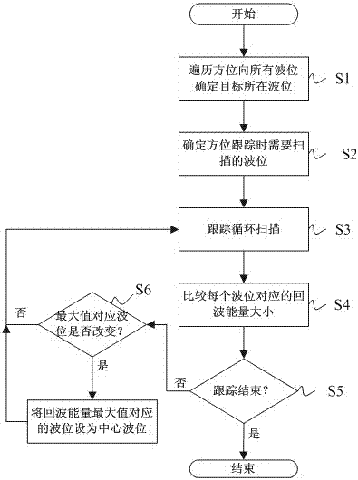
The invention discloses a phased array beam tracking method. The method includes the steps that an annular syntype phased array traverses all wave potentials on an azimuth by controlling beams on the azimuth, and a wave potential of the azimuth where a tracking target is located is determined; the wave potential on the azimuth is controlled to point to the wave potential where the tracking target is located, and the wave potential serves as a center wave potential of tracking loop scanning; the center wave potential serves as the center of the annular syntype phased array, tracking loop scanning is carried out on three wave potentials in adjacent airspaces of the tracking target, and target echo energy is recorded; the annular syntype phased array compares the magnitudes of the target echo energy of the three wave potentials in the adjacent airspace of the tracking target, and the wave potential where the target echo energy is largest is determined to be a center wave potential of next tracking circulating scanning. The direction of the target is determined according to the magnitudes of the target echo energy, the phased array achieves a beam tracking function on the azimuth, complexity of phased array design is effectively reduced, design space is reduced and miniaturization design of the phased array is facilitated.

Description

technical field [0001] The invention relates to the field of phased array beam control, in particular to a phased array beam tracking method. Background technique [0002] Existing phased array radar systems mainly rely on sum and differential power division networks to realize angle measurement and beam tracking functions. The phased array radar forms the sum and difference pattern of the antenna through the sum and difference power division network, and the phased array radar controls the transceiver (TR) unit to receive the target echo signal, and forms the sum channel signal and the difference channel signal after passing through the sum and difference power division network. The signal processor of the phased-array radar performs sum-difference ratio and phase angle measurement on the sum-difference channel signal, calculates the radar angle error of the target in azimuth and elevation, and performs closed-loop control on the beam pointing through the radar angle error ...

Claims


Application Information

Patent Timeline
Patent Type & Authority Patents(China)
IPC IPC(8): G01S13/72
CPCG01S13/68G01S2013/0245
Inventor 余渝生王志诚邹波朱骏
Owner SHANGHAI RADIO EQUIP RES INST
Learn More