A Pneumatic Gripper Device with Rotatable Product Position

A gripper device and attitude technology, applied in the directions of manipulators, manufacturing tools, chucks, etc., can solve the problems of not adapting to the connection requirements of automated production lines, single function, only clamping and grasping, loosening and releasing, etc.

Inactive Publication Date: 2017-01-18
宁波点鑫工贸有限公司
View PDF5 Cites 0 Cited by
  • Summary
  • Abstract
  • Description
  • Claims
  • Application Information

AI Technical Summary

Problems solved by technology

[0002] The manipulator used to automatically remove injection molded products from the mold of the injection molding machine is referred to as the manipulator. The manipulator is composed of a mechanical arm elbow and a mechanical gripper. The mechanical gripper is referred to as the gripper. The gripper of the technology only has the function of clamping and grabbing, releasing and releasing the product; for the automatic production line that needs to be able to automatically rotate the product after grabbing the product, and coordinate with the next automatic processing program, the existing technology has simple actions , the function is single, and it is difficult to meet the demand; therefore, the existing technology has the problems and deficiencies of the single function and not being suitable for the connection requirements of the automated production line

Method used


Image

  • A Pneumatic Gripper Device with Rotatable Product Position
  • A Pneumatic Gripper Device with Rotatable Product Position
  • A Pneumatic Gripper Device with Rotatable Product Position

Examples


Embodiment Construction

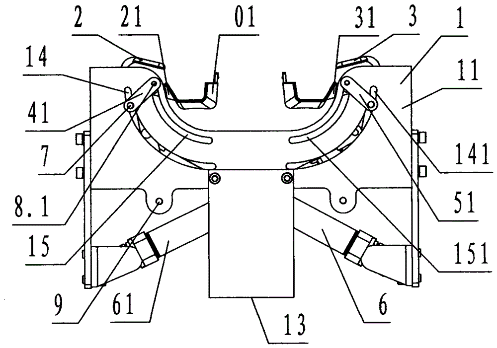
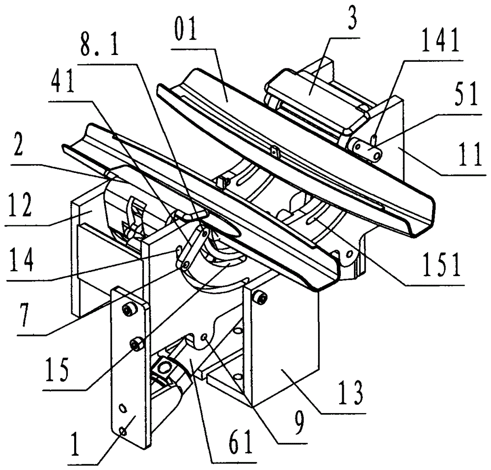
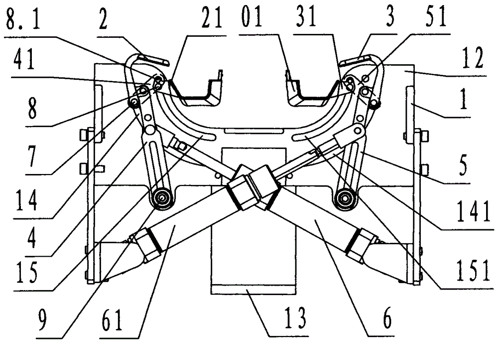
[0028] refer to Figure 1 to Figure 7, a pneumatic gripper device with a rotatable product posture according to the present invention, comprising a base 1, an upper left sliding claw 2, a left sliding claw 21, an upper right sliding claw 3, a right sliding claw 31, a left upper claw connecting rod 4, a left lower claw connecting rod Rod 41, right upper claw connecting rod 5, right lower claw connecting rod 51, left cylinder 6, right cylinder 61, upper rotating shaft 7, lower rotating shaft 8, lower moving shaft 8.1, guide shaft 9, wherein: described base 1 is A rectangular frame-shaped steel member with an open top and a bottom bottom surrounded by steel plates, the bottom wall below the center of the base 1 is called the connecting frame 13; the front and rear walls of the base 1 are called the front wall 11 respectively And the rear wallboard 12; the middle and upper part of the rear wallboard 12 is provided with a rectangular through groove called an avoidance groove, and a...


PUM


Abstract

The invention discloses a pneumatic gripper device capable of rotating postures of products. The pneumatic gripper device capable of rotating the postures of the products comprises a base (1), an upper left sliding gripper (2), a lower left sliding gripper (21), an upper right sliding gripper (3), a lower right sliding gripper (31), an upper left gripper connection rod (4), a lower left gripper connection rod (41), an upper right gripper connection rod (5), a lower right gripper connection rod (51), a left cylinder (6), a right cylinder (61), an upper rotation shaft (7), a lower rotation shaft (8), a lower movable shaft (8.1) and a guide shaft (9). According to the device formed by the components, an upper left gripper rail, a lower left gripper rail, an upper right gripper rail and a lower right gripper rail are arranged on the base; when the device works, the left cylinder and the right cylinder respectively and simultaneously grip a left product and a right product from an injection mold by the upper left sliding gripper, the lower left sliding gripper, the upper right sliding gripper and the lower right sliding gripper which are driven by the upper left gripper connection rod, the lower left gripper connection rod, the upper right gripper connection rod and the lower right gripper connection rod; according to the technical scheme, the products are released from the injection mold under the guide of the upper left gripper rail, the lower left gripper rail, the upper right gripper rail and the lower right gripper rail; then the left product is clamped by the upper left sliding gripper and the lower left sliding gripper to counterclockwise rotate at 60 degrees; the right product is clamped by the upper left sliding gripper and the lower left sliding gripper to clockwise rotate at 60 degrees and is transferred into a next station, so that a mechanical gripper has various functions and meets the connection requirements of an automatic production line.

Description

technical field [0001] The invention relates to a gripper device, in particular to a pneumatic gripper device with a rotatable product posture used for automatically removing an injection molded product manipulator from a mold of an injection molding machine. Background technique [0002] The manipulator used to automatically remove injection molded products from the mold of the injection molding machine is referred to as the manipulator. The manipulator is composed of a mechanical arm elbow and a mechanical gripper. The mechanical gripper is referred to as the gripper. The gripper of the technology only has the function of clamping and grabbing, releasing and releasing the product; for the automatic production line that needs to be able to automatically rotate the product after grabbing the product, and coordinate with the next automatic processing program, the existing technology has simple actions , the function is single, and it is difficult to meet the demand; therefore...

Claims


Application Information

Patent Timeline
Patent Type & Authority Patents(China)
IPC IPC(8): B29C45/42B25J15/10
CPCB25J15/10B29C45/42B29C2045/4241
Inventor 周丰泉何建阳
Owner 宁波点鑫工贸有限公司
Why Eureka
Try Eureka