
Bending device for automobile component

A bending device, a technology for auto parts, applied in the field of auto parts processing, can solve the problems of reducing the strength of parts, easy offset bending of parts, uneven force, etc. wear effect

Inactive Publication Date: 2015-01-21
重庆市大足区万鑫卷闸门配件厂
View PDF1 Cites 7 Cited by
  • Summary
  • Abstract
  • Description
  • Claims
  • Application Information

AI Technical Summary

Problems solved by technology

[0002] There are many kinds of auto parts, some need to be bent, and the bending position is very small and fragile. When bending with a conventional bending device, because the applied force cannot be dispersed, it is easy to cause excessive force on the bending position Or uneven stress leads to breakage, which is not easy to guarantee the yield of the product
[0003] In the prior art, the "Bending Device for Auto Parts" with the application number 201320772859.5 mainly has the following disadvantages: 1. The bending process requires a lot of pressure, the internal structure of the parts is easily damaged, the strength of the parts is reduced, and the probability of breaking is high ;2. During the bending process, the parts are easy to bend and bend, resulting in more waste products and lower yield

Method used


Image

  • Bending device for automobile component
  • Bending device for automobile component

Examples


Embodiment Construction

[0014] The principles and features of the present invention are described below in conjunction with the accompanying drawings, and the examples given are only used to explain the present invention, and are not intended to limit the scope of the present invention.

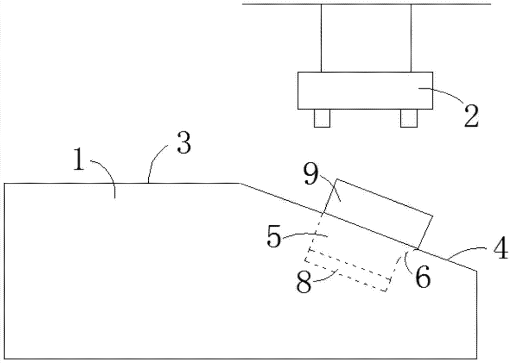
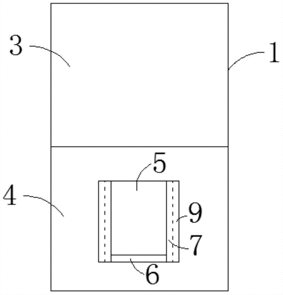
[0015] Such as figure 1 and figure 2 As shown, a bending device for automobile parts includes a base 1, a pressing device 2 for bending parts and a fixing block 3, the pressing device 2 is placed above the base 1, and the base 1 includes Horizontal plane 3 and lower inclined plane 4, described lower inclined plane 4 is placed directly below described pressing device 2, and described horizontal plane places 3 on one side of described lower inclined plane 4, and is connected with described horizontal plane 3, and described lower inclined plane 4 A positioning groove 5 is provided on the inclined surface 4 relative to the vertical coaxial line of the pressing device 2, and a circular arc transition surface 6 is provi...


PUM


Abstract

The invention relates to a bending device for an automobile component. The bending device comprises a base, a pressing device bending the component, and fixing blocks. The pressing device is arranged above the base. The base comprises a horizontal plane and a downwards-inclined plane. The downwards-inclined plane is arranged under the pressing device. The horizontal plane is arranged on one side of the downwards-inclined plane. The downwards-inclined plane is connected with the horizontal plane. A positioning groove is formed in the vertical coaxial line, opposite to the pressing device, of the lower inclined plane, a circular arc transition plane is arranged on the relatively low side of the positioning groove in the horizontal direction, and the two fixing blocks are fixedly arranged on the two sides of the positioning groove respectively and located on the two sides of the circular arc transition plane. Heating devices are embedded in the faces, close to the positioning groove, of the two fixing blocks. Compared with the prior art, the bending device is simple in structure, deflection bending can be reduced, the product yield and the product quality can be improved, and energy consumption can be reduced.

Description

technical field [0001] The invention relates to the technical field of auto parts processing, in particular to a bending device for auto parts. Background technique [0002] There are many kinds of auto parts, some need to be bent, and the bending position is very small and fragile. When bending with a conventional bending device, because the applied force cannot be dispersed, it is easy to cause excessive force on the bending position Or the uneven force will lead to breakage, which is not easy to guarantee the yield of the product. [0003] In the prior art, the "Bending Device for Auto Parts" with the application number 201320772859.5 mainly has the following disadvantages: 1. The bending process requires a lot of pressure, the internal structure of the parts is easily damaged, the strength of the parts is reduced, and the probability of breaking is high ; 2. During the bending process, the parts are easy to be bent out of position, resulting in more waste products and l...

Claims


Application Information

Patent Timeline
Patent Type & Authority Applications(China)
IPC IPC(8): B21D11/00B21D11/22
CPCB21D11/00B21D11/22B21D37/16
Inventor 万庆群
Owner 重庆市大足区万鑫卷闸门配件厂
Learn More