Multi-core plastic optical fiber port device and system
A technology of plastic optical fiber and interface equipment, which is applied in optical fiber transmission, light guide, optics, etc., can solve the problems of restricting the development of multi-core plastic optical fiber, high cost, and large volume, and achieve low cost, saving wiring costs, and small volume.
- Summary
- Abstract
- Description
- Claims
- Application Information
AI Technical Summary
Problems solved by technology
Method used
Image
Examples
Embodiment 1
[0050] Embodiment 1: a multi-core plastic optical fiber simplex interface device.
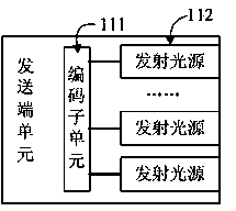
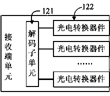
[0051] Figure 4 As shown, it is a schematic diagram of a multi-core plastic optical fiber simplex interface device, including a switching chip 20; three physical layer chips 211, 212, 213; a multi-core plastic optical fiber receiving end unit 221 and two multi-core plastic optical fiber sending End unit 222,223; There is also a power management module 23. Wherein, three physical layer chips 211,212,213 and the power management module 23 are directly connected with the switching chip 20, the multi-core plastic optical fiber receiving end unit 221 and two multi-core The core plastic optical fiber transmitting end units 222, 223 are respectively connected to corresponding physical layer chips 211, 212, 213.
[0052] The multi-core plastic optical fiber simplex interface device can be used for the transfer and distribution of plastic optical fiber signals. The multi-core plastic optical fiber r...
Embodiment 2
[0055] Embodiment 2: A multi-core plastic optical fiber duplex interface device.
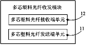
[0056] Figure 5 As shown, it is a schematic diagram of a multi-core plastic optical fiber duplex interface device, including a switch chip 30; three physical layer chips 311, 312, 313; three multi-core plastic optical fiber transceiver modules 321, 322, 323 and a power management Module 33. Among them, the three physical layer chips 311, 312, 313 are directly connected with the power management module 33 and the switching chip 30, and the three multi-core plastic optical fiber transceiver modules 321, 322, 323 are respectively connected to the corresponding physical layer chips 311, 312, 313 .
[0057] The multi-core plastic optical fiber interface device can be used for the transfer and distribution of plastic optical fiber signals. The information obtained by any one of the multi-core plastic optical fiber transceiver modules 321, 322, 323 will be transmitted to the switching chip 30 throu...
Embodiment 3
[0068] Embodiment 3: a multi-core plastic optical fiber router.
[0069] Figure 7 Shown is a multi-core plastic optical fiber router structure diagram. The router includes a routing chip 40, four physical layer chips 411-414, three multi-core plastic optical fiber interfaces 421-423, and an Ethernet interface 424. In addition, the router also includes a power management module (not shown in the figure). The Ethernet port 424 is connected to the routing chip 40 through the physical layer chip 414 , the multi-core plastic optical fiber interfaces 421 - 423 are respectively connected to the routing chip 40 through the physical layer chips 411 - 413 , and the power management module is also directly connected to the routing chip 40 .
[0070] The Ethernet interface 424 has a built-in Ethernet module, which can send network signals to the routing chip 40 through the physical layer chip 414 . The routing chip 40 will automatically select and set the route according to the channel...
PUM
 Abstract
Description
Claims
Application Information
 - R&D Engineer
- R&D Manager
- IP Professional
- Industry Leading Data Capabilities
- Powerful AI technology
- Patent DNA Extraction
Browse by: Latest US Patents, China's latest patents, Technical Efficacy Thesaurus, Application Domain, Technology Topic, Popular Technical Reports.
© 2024 PatSnap. All rights reserved.Legal|Privacy policy|Modern Slavery Act Transparency Statement|Sitemap|About US| Contact US: help@patsnap.com


