
Low-voltage differential signal driver

A low-voltage differential signal and driver technology, applied in the direction of logic circuit connection/interface layout, etc., can solve the problems of device characteristics and mismatch sensitivity, common-mode level shift and fluctuation, limit circuit application, etc., to improve the charging and discharging speed , improve stability and work speed, and reduce the effect of impact

Inactive Publication Date: 2015-01-14
XIDIAN UNIV
View PDF5 Cites 7 Cited by
  • Summary
  • Abstract
  • Description
  • Claims
  • Application Information

AI Technical Summary

Problems solved by technology

[0004] Due to the noise inside and outside the chip and the change of PVT during work, it is easy to cause the shift and fluctuation of the common mode level in the signal transmission process, which is difficult to ensure that the requirements of the LVDS international standard are met, and the output common mode level has a great influence on the characteristics of the device. quite sensitive to mismatch and cannot be stabilized by differential feedback
Therefore, for this traditional structure, it is impossible to accurately realize the common-mode level of the output LVDS signal in the LVDS driver, and it is necessary to add a common-mode feedback circuit to stabilize the output common-mode level
And due to the existence of the parasitic capacitance of the output node, the working speed of the circuit is seriously restricted, which greatly limits the application of this circuit in high-speed occasions.

Method used


Image

  • Low-voltage differential signal driver
  • Low-voltage differential signal driver
  • Low-voltage differential signal driver

Examples


Embodiment Construction

[0038] In order to make the technical problems, technical solutions and advantages to be solved by the present invention clearer, the following will describe in detail with reference to the drawings and specific embodiments.

[0039] Such as image 3 As shown, an embodiment of the present invention provides a low-voltage differential signal driver, including:

[0040] The main drive circuit is used to generate high-speed differential transmission data with low voltage swing;

[0041] a common-mode feedback network, connected to the main body driving circuit, for comparing the common-mode voltage at the output terminal of the main body driving circuit with a target common-mode voltage, so as to adjust the common-mode voltage to the target common-mode voltage Level.

[0042] Wherein, the main body drive circuit includes:

[0043] The first NMOS transistor M1, the second NMOS transistor M2, the third NMOS transistor M3, the fourth NMOS transistor M4, the fifth NMOS transistor ...


PUM


Abstract

The invention provides a low-voltage differential signal driver. The low-voltage differential signal driver comprises a main driving circuit and a common-mode feedback network. The main driving circuit is used for generating high-speed differential transmission data with low voltage swing. The common-mode feedback network is connected with the main driving circuit and used for comparing common-mode voltage at the output end of the main driving circuit with target common-mode voltage so as to adjust the common-mode voltage to the level of the target common-mode voltage. The low-voltage differential signal driver greatly improves the stability of the driving circuit and increases the working speed of the driving circuit.

Description

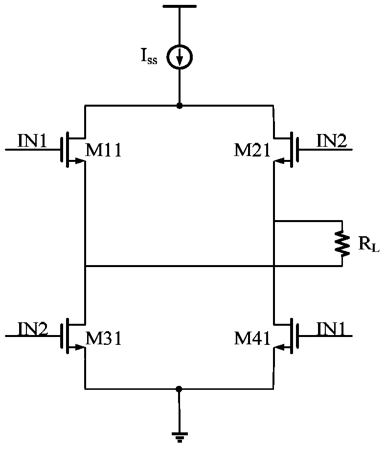
technical field [0001] The invention relates to the field of circuit technology, in particular to a low-voltage differential signal driver. Background technique [0002] LVDS (Low Voltage Differential Signaling) is a data transmission and interface technology that only appeared in the 1990s. The core of this technology is high-speed differential data transmission with extremely low voltage swing, which can realize point-to-point or point-to-multipoint connection, and has the characteristics of low power consumption, low bit error rate, low crosstalk and low radiation. [0003] A typical LVDS driver is a current source that switches current direction at high speed, and the output current establishes the correct differential output voltage swing across the load resistor. Such as figure 1 The traditional LVDS driver shown, includes: four transistors M11, M21, M31, M41 and a load resistor R L , wherein, the gates of transistors M11 and M41 are connected to the input signal IN...

Claims


Application Information

Patent Timeline
IPC IPC(8): H03K19/0175
Inventor 朱樟明关宇恒赵磊丁瑞雪杨银堂
Owner XIDIAN UNIV
Learn More