


Quick Research
Generate reliable direction feasibility study reports for your R&D in just a few steps.

Technical Q&A
Discover and master advanced knowledge NOW. Basics, ideas, possibilities, all at once.

Find Solutions
As an expert in R&D theories, this can generate solutions to your technical problems instantly.

Evaluate Feasibility
Analyze your overall solution with one click, know your potential R&D risks in advance.

Monitor Landscape
Get weekly tech updates, stay abreast of the latest tech innovations and key insights.
Projector
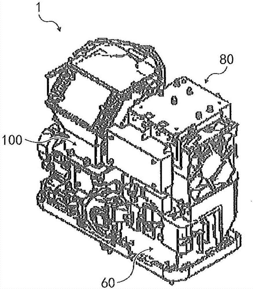
An image projection and image technology, which is applied in the direction of using a projection device, an image reproducer, a projection device, and image communication, etc., can solve the problems of increasing the noise of the exhaust fan 86 and the like.
- Summary
- Abstract
- Description
- Claims
- Application Information
AI Technical Summary
Problems solved by technology
Method used
Image


Examples
Embodiment approach
[0117] One embodiment of the present invention has been described above, and various embodiments of the present invention described below have their own unique effects.
Embodiment approach 1
[0119] Image projecting device such as projector 1 etc., has light source 61; Image forming part 101, uses the light that light source 61 emits to irradiate image generating elements such as DMD12, generates optical image; Generated optical image; power supply unit 80, to supply power to light source 61; frame body (in this embodiment, constitute as exterior cover 59 and base member 53 etc.), be used for accommodating light source 61, image forming unit 101, projection optics unit 102 , and the power supply unit 80, the outside air is sucked in from the first air inlet 84 provided on the frame body, and the outside air flows around the projection optical unit 102 to the power supply unit 80 to cool the power supply unit 80, and the cooled air flows from the The exhaust port 85 on the frame is exhausted, wherein, the second air inlet 131 is set, and the second air inlet 131 is closer to the power supply part 80 than the first air inlet 84, and the air is sucked from the second a...
Embodiment approach 2
[0122] In Embodiment 1, the total opening cross-sectional area of the second air inlet 131 is 300 mm. 2 above.
[0123] According to this, in Embodiment 2, the outside air can be sucked in efficiently through the second air inlet 131 .
PUM
 Abstract
Description
Claims
Application Information
 - R&D Engineer
- R&D Manager
- IP Professional
- Industry Leading Data Capabilities
- Powerful AI technology
- Patent DNA Extraction
Browse by: Latest US Patents, China's latest patents, Technical Efficacy Thesaurus, Application Domain, Technology Topic, Popular Technical Reports.
© 2024 PatSnap. All rights reserved.Legal|Privacy policy|Modern Slavery Act Transparency Statement|Sitemap|About US| Contact US: help@patsnap.com