
Head-mounted display lens assembly testing machine

A technology of lens components and testing machines, which is applied in the direction of testing optical performance, etc., and can solve problems such as the lack of a unified industry standard

Active Publication Date: 2018-01-02
GOERTEK OPTICAL TECH CO LTD
View PDF5 Cites 0 Cited by
  • Summary
  • Abstract
  • Description
  • Claims
  • Application Information

AI Technical Summary

Problems solved by technology

[0003] At present, many companies have launched their own head-mounted displays one after another. However, because the current technology is not yet mature, has not passed the actual market test, and has not formed a unified industry standard, so various professional equipment supporting the production of head-mounted displays has not yet appeared.

Method used


Image

  • Head-mounted display lens assembly testing machine
  • Head-mounted display lens assembly testing machine
  • Head-mounted display lens assembly testing machine

Examples


Embodiment 1

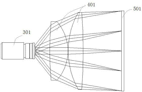
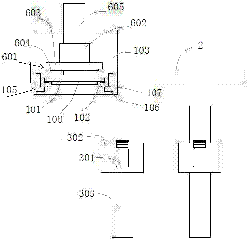
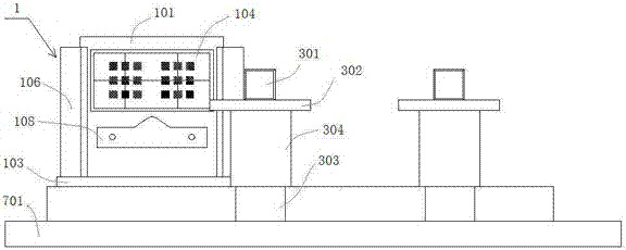
[0027] Embodiment 1, a head-mounted display lens assembly testing machine of this embodiment, its principle is as follows figure 1 As shown, the image receiving device 301 is set at the position of the human eye, instead of the human eye, the image imaged on the display 501 is received through the lens assembly 401, and the image is taken, so that the head-mounted display can be analyzed by analyzing the image in the later stage. Information about lens components. Such as Figure 2-Figure 3 As shown, it is a top view of the head-mounted display lens assembly testing machine proposed in this embodiment, which includes a clamping part 1 for fixing and supporting the lens assembly, and is used to drive the clamping part 1 along the horizontal plane with the lens. The first driving mechanism 2 that moves in the direction perpendicular to the optical axis of the component, and the image receiving device 301 arranged on one side of the clamping part 1, such as image 3 As shown, i...

Embodiment 2

[0036] Embodiment 2, a head-mounted display lens assembly testing machine of this embodiment is suitable for aligning the best back focus of the lens assembly. On the one hand, it can guide the installation of the display and the lens assembly of the head-mounted display. On the other hand, it can It is used to test the best back focus of the left eye and the right eye respectively, and judge whether the error of the best back focus of the two is within the allowable range, so as to verify whether the product is qualified. Since it is not necessary to be fixed on the clamping part 1 together with the display and the lens assembly, as figure 2 As shown, only the display unit 601 needs to be provided on the opposite side of the clamping part 1 to the image receiving device 301 for imaging by simulating a display. The display unit 601 is arranged on the first substrate 103, the display unit 601 is arranged on the other side of the clamping part 1, and is arranged on the first su...


PUM


Abstract

The invention discloses a head-mounted display lens component testing machine, which comprises a clamping part for fixing and supporting the lens component, and is used for driving the clamping part to move on a horizontal plane along a direction perpendicular to the optical axis of the lens component. The first driving mechanism and the image receiving device arranged on one side of the clamping part, the first driving mechanism drives the clamping part to move and then drives the lens assembly to move so that the optical axis of the lens assembly is in line with the The optical axes of the image receiving devices are aligned. In the head-mounted display lens component testing machine of the present invention, the image receiving device is arranged at the position of the human eye, and replaces the human eye to receive the image imaged on the display through the lens component and take pictures to obtain the relevant information of the head-mounted display lens component. information, especially for testing optical components in head-mounted displays.

Description

technical field [0001] The invention relates to the technical field of optical lens assembly testing, in particular to a head-mounted display lens assembly testing machine. Background technique [0002] As an emerging technology in recent years, head-mounted display (HMD) is a kind of enlarged image on the ultra-micro display screen, which projects the image on the user's retina, and then presents a large-screen image in the eyes of the viewer. Head-mounted displays are currently widely used in many aspects such as industry, military affairs, literature and art, and entertainment. [0003] At present, many companies have launched their own head-mounted displays one after another. However, because the current technology is not yet mature, has not passed the actual market test, and has not formed a unified industry standard, so various professional equipment supporting the production of head-mounted displays has not yet appeared. . [0004] Based on this, how to invent a mac...

Claims


Application Information

Patent Timeline
Patent Type & Authority Patents(China)
IPC IPC(8): G01M11/02
Inventor 赵博刚杨春
Owner GOERTEK OPTICAL TECH CO LTD
Learn More