
Twisting device of direct twisting machine

A technology of twisting device and direct twisting machine, which is applied in the direction of textiles and papermaking, etc. It can solve the problems of shortening the service life of the electric spindle motor, the easy bending of the electric spindle shaft, and motor damage, etc., and achieves the increase of wear-resistant material top cover and the reduction of breakage. Yarn phenomenon, the effect of extending the service life

Inactive Publication Date: 2015-01-14
ZHANGJIAGANG JUNMA POLYESTER PROD
View PDF9 Cites 3 Cited by
  • Summary
  • Abstract
  • Description
  • Claims
  • Application Information

AI Technical Summary

Problems solved by technology

The twisting device of the existing direct twisting machine has the following defects: (1) The weight of the twist leveler, the inner yarn tensioner, and the spindle pot is directly stressed on the electric spindle motor. Under the condition of high-speed rotation, the electric spindle motor is easily damaged. Shorten the service life of the electric spindle motor; (2) At present, the guide wheel adopts the double-bearing outer shell structure, and no lubricating oil can be added. When one of the bearings is stuck, the yarn cannot be wound, and the twist leveler Deviated to one side, causing the ingot tank to tilt and the bearing to be damaged. At the same time, the electric spindle shaft of the electric spindle motor is easy to bend, causing damage to the motor; (3) In the initial stage of starting the direct twisting machine, the speed of the yarn is slow and easily connected with the internal tensioner. Edge contact, causing yarn breakage

Method used

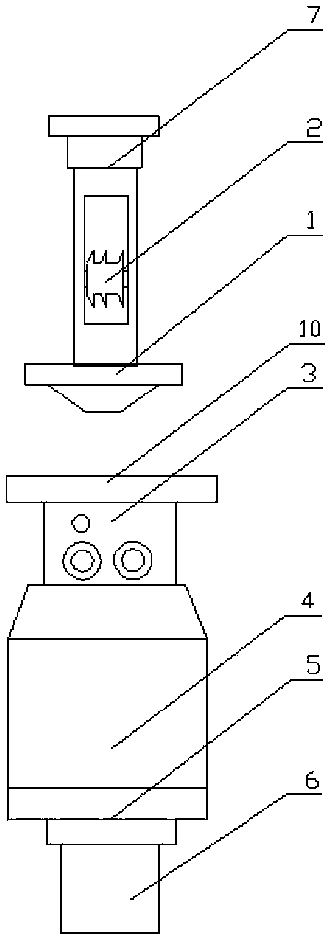

Image

  • Twisting device of direct twisting machine
  • Twisting device of direct twisting machine
  • Twisting device of direct twisting machine

Examples


Embodiment Construction

[0013] See figure 1 , the present invention has a twist leveler 1, a guide wheel 2, an inner yarn tensioner 3, a spindle pot 4, a spindle 5, and an electric spindle motor 6; the middle part of the twist leveler 1 is a hollow structure, and the upper part has a lightweight shock-absorbing connection device 7 for A circular nylon shock-absorbing connection block, the twist leveler 1 is fixedly connected to the wallboard above the twisting device of the straight twisting machine through the shock-absorbing connection device 7.

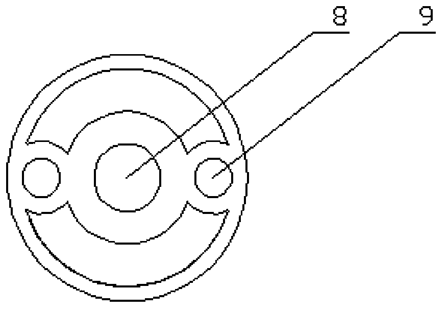
[0014] The middle part of the nylon damping connection block has a through hole 8, and the two ends of the through hole 8 are screw holes 9. The bolts are fixed on the wallboard of the straight twisting machine through the screw holes 9, and there are symmetrical weight-reducing grooves on the nylon damping block.

[0015] The guide wheel 2 is fixed at the position below the hollow structure of the twist leveler 1 through the mandrel; it is a double ball ...


PUM


Abstract

The invention relates to a twisting device of a direct twisting machine. The twisting device comprises a uniform twisting device, a guide wheel, an inner yarn tensioning device, a spindle tank, a spindle and an electric spindle motor, wherein the middle part of the uniform twisting device is of a hollow structure and the upper part of the uniform twisting device is provided with a light-weight shock absorption connection device; the uniform twisting device is fixedly connected with a wall plate above the twisting device of the direct twisting machine through the shock absorption connection device. The stress of the electric spindle motor is alleviated by changing the mounting position of the uniform twisting device; the structure of the guide wheel is changed, so that the clamping phenomenon of the guide wheel is avoided and the service life of the electric spindle motor is prolonged; furthermore, a top cover made of a wear-resisting material of the inner yarn tensioning device is additionally arranged, so that a yarn breaking phenomenon is effectively reduced.

Description

technical field [0001] The invention relates to a twisting device, in particular to a twisting device for a straight twisting machine. Background technique [0002] Twisting is an important part of the spinning process. Twisting is to combine two or more strands of yarn into one strand, and then add a certain twist to this ply yarn to make it a yarn. Direct twisting machine is a kind of yarn mainly used to introduce two strands of yarn from two yarn packages, one of which is installed in the rotating spindle, and the other strand of yarn passes through the twisting disc of the spindle. , passing outside the spindle, and then the two strands of yarn are merged into the leveler to form an inner yarn and an outer yarn, and the outer yarn will form a balloon during the rotation of the spindle. The twisting device of the existing direct twisting machine has the following defects: (1) The weight of the twist leveler, the inner yarn tensioner, and the spindle pot is directly stres...

Claims


Application Information

Patent Timeline
Patent Type & Authority Applications(China)
IPC IPC(8): D01H7/02
CPCD01H7/02
Inventor 蒋卫祥
Owner ZHANGJIAGANG JUNMA POLYESTER PROD
Learn More