
Dynamic Scheduling And Time Control For Intelligent Bus System

A public transport system and bus technology, applied in the field of dynamic scheduling and time management of intelligent public transport systems, can solve the problems of electronic navigation vehicles not being able to follow, not reflecting the real position of electronic navigation vehicles, etc.

Inactive Publication Date: 2015-01-07
TOMORROWS TRANSPORTATION TODAY
View PDF7 Cites 43 Cited by
  • Summary
  • Abstract
  • Description
  • Claims
  • Application Information

AI Technical Summary

Problems solved by technology

Therefore, position estimates derived from such measurements do not reflect the true position of the electronically guided vehicle relative to either magnetic marker or track, resulting in the electronically guided vehicle not being able to follow either of the two magnetic tracks

Method used


Image

  • Dynamic Scheduling And Time Control For Intelligent Bus System
  • Dynamic Scheduling And Time Control For Intelligent Bus System
  • Dynamic Scheduling And Time Control For Intelligent Bus System

Examples


Embodiment Construction

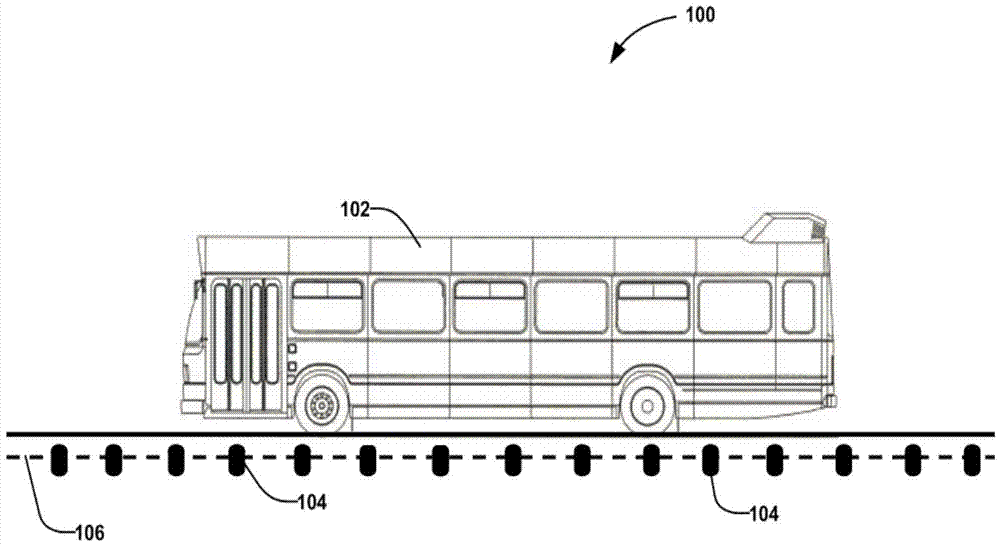
[0054] figure 1 An electronically guided bus 102 is shown capable of automatically following a magnetic track 106 defined by magnetic markers (magnetic markers) 104 installed in the lane. The magnetic marker 104 is usually a permanent magnet installed under the road surface with one pole (north or south) facing upwards. The magnetic marker 104 may be mounted along the centerline of the roadway or at a predetermined offset (or more) from the centerline of the roadway. The distance between two adjacent magnetic markers 104 may be a fixed distance (for example, 1 meter) or may vary according to the curvature of the lane or other considerations.

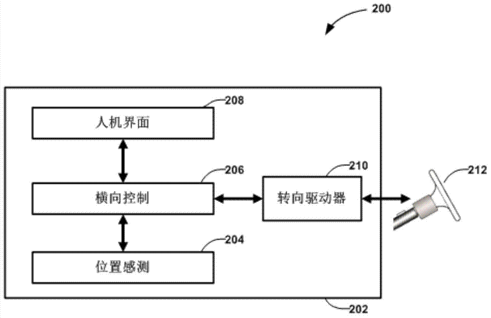
[0055] figure 2 is a block diagram 200 of an onboard electronic guidance system 202 installed on an electronically guided bus 102 . The electronic guidance system 202 enables the electronically guided bus 102 to automatically follow the magnetic track 106 defined by the magnetic markers 104 . The position sensing unit 204 determines...


PUM


Abstract

The invention provides a method for providing dynamic scheduling for buses in a team-grouping manner of a bus system. The method includes determining a service interval for each travel of the bus system, determining the combination of the bus teams according to the service interval of each travel, determining the scheduling time table of each bus according to the travel service interval and the team combination, transmitting the scheduling time table to each bus and transmitting the team combination to each bus too. A plurality of buses are grouped into a team in their shared road sections, so that buses having different travels can stop by stations at the same time like trains for making convenience for passengers to transfer.

Description

technical field [0001] The invention relates to a dispatching method and system for dynamically dispatching electronic guidance buses based on real-time passenger flow demands and traffic conditions. More specifically, the method provided by the present invention can allow the electronically guided bus to automatically select the electronic track to follow according to the assigned itinerary, and allow the bus dispatching system to dynamically plan the bus itinerary and determine the dispatching time according to the real-time passenger flow demand surface. Background technique [0002] In recent decades, developing low-cost, efficient, high-performance public transport systems for modern cities has attracted a lot of attention. Many metropolises have built subways. However, due to the high cost of the subway, the subway is usually used when a very large passenger flow needs to be met. Some cities have chosen to build light rail systems that combine the appeal of traditio...

Claims


Application Information

Patent Timeline
Patent Type & Authority Applications(China)
IPC IPC(8): G08G1/00G08G1/09
CPCG08G1/202G05D1/0261G05D1/0297G08G1/133G08G1/22B60W10/04B60W10/18B60W10/20B60W30/12B60W30/14B60W2300/10B60W2710/0666B60W2710/202B60Y2200/143G06Q50/26G06Q10/06314B60W2520/10B60W2720/10B60W2554/804B60W2556/45B60W2554/801B60W2556/65B60W2754/30
Inventor 黄继华张维斌但汉曙
Owner TOMORROWS TRANSPORTATION TODAY
Learn More