Clutch assisting device

A technology of booster and clutch, applied in clutch, filter separation, separation method, etc., can solve the problems of clutch booster failure, easy to pull cylinder block and seals, etc., and achieve the effect of avoiding damage

Inactive Publication Date: 2015-01-07
CHONGQING JINLUN IND
View PDF0 Cites 2 Cited by
  • Summary
  • Abstract
  • Description
  • Claims
  • Application Information

AI Technical Summary

Problems solved by technology

With the prolongation of the use time, the dust entering the cylinder block will accumulate more and more, and some of the dust will undergo chemical changes and solidify into hard lumps after a long time. During the working process of the clutch booster, it is easy to strain the cylinder block and seals. , causing the clutch booster to fail

Method used


Image

  • Clutch assisting device

Examples


Embodiment Construction

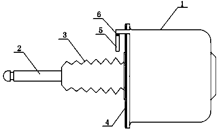
[0009] The present invention will be further described below in conjunction with accompanying drawing.

[0010] Such as figure 1 As shown, the present invention provides a clutch booster, comprising a cylinder 1, a push rod 2 and a dust cover 3, the dust cover 3 adopts a corrugated connection circular tube, and one end of the dust cover 3 is sealed and fixedly connected with the push rod 2, The other end of the dust cover 3 is sealed and fixedly connected with the front cover plate 4 of the cylinder. Since the force here is small, the sealant connection can be used to ensure that the dust cover 3 is a fully sealed structure. The upper part of the front cover plate 4 of the cylinder is provided with a ventilation pipe 5. The ventilation pipe 5 is in an inverted L shape. One end of the ventilation pipe 5 communicates with the cylinder 1, and the other end of the ventilation pipe 5 communicates with the outside world and faces downward. An air filter device is arranged in the ai...


PUM


Abstract

The invention relates to a clutch control mechanism for automobile transmission, in particularly to a clutch assisting device. The clutch assisting device comprises an air cylinder, a push rod and a dustproof cover; one end of the dustproof cover is in sealing connection with the push rod; the other end of the dustproof cover is in sealing connection with a front cover plate of the air cylinder; the dustproof cover is in a full-sealing structure; the front cover plate of the air cylinder is provided with a ventilation pipe; the ventilation pipe is in a reversed L shape; one end of the ventilation pipe is communicated with the air cylinder; the other end of the ventilation pipe is communicated with the exterior; a connecting end of the ventilation pipe and the air cylinder is higher than that of the ventilation pipe and the exterior; an air filtration device is arranged inside the ventilation pipe. According to the technical scheme of the clutch assisting device, the structure is simple, the dustproof effect is good, the service life of the clutch is prolonged, and convenience is brought to a user.

Description

technical field [0001] The invention relates to a clutch control mechanism for automobile transmission, in particular to a clutch booster device. Background technique [0002] The heavy-duty vehicle clutch booster is usually connected to the clutch housing at the front of the gearbox, and uses high-pressure air to push the clutch to disengage. During the working process, the reciprocation of the piston in the cylinder will produce respiration. The air hole of the existing clutch booster is located on the dust cover at the front of the clutch booster, and the layout of the clutch booster is generally low in height from the ground, so that the clutch booster is in a dust-intensive environment. Under the action of respiration produced by the reciprocating movement of the piston, since the vent hole directly communicates with the air, the dust in the air will enter the interior of the cylinder block from the vent hole along with the breathing airflow. With the prolongation of ...

Claims


Application Information

Patent Timeline
IPC IPC(8): F16D48/04F16J15/52B01D35/02
Inventor 吴明喜
Owner CHONGQING JINLUN IND
Why Eureka
Try Eureka