
Individual bush separation mechanism of automatic identifying bush loader

An automatic identification and separation mechanism technology, applied in the direction of auxiliary devices, auxiliary welding equipment, welding/cutting auxiliary equipment, etc., can solve the problems of solder melting splash, scrap amount, precision bushing without gaps, etc., to achieve high identification efficiency, The effect of fast feeding speed

Inactive Publication Date: 2015-01-07
SUZHOU ISHIMARU ERI PML PRECISION MECHANISM CO LTD
View PDF10 Cites 0 Cited by
  • Summary
  • Abstract
  • Description
  • Claims
  • Application Information

AI Technical Summary

Problems solved by technology

[0002] The bushing is a necessary wear-resistant product for some moving joints in the automation equipment. Its main purpose is to reduce the wear of the joint body of the equipment. Adjust the gap, but the precision bushing cannot have gaps. It needs to be welded to complete, but the existing processes are all manually discharged to the fixture and then completed by solder welding. During the welding process, manual feeding and welding are required. The solder will melt and splatter during welding, producing solder slag, and there will be a certain amount of scrap during welding.
Welding is done manually, so the efficiency is relatively low. Fully automatic welding machines need to be automatically loaded to complete, and the efficiency of manual identification of weld seams is very low.

Method used


Image

  • Individual bush separation mechanism of automatic identifying bush loader
  • Individual bush separation mechanism of automatic identifying bush loader

Examples


Embodiment Construction

[0008] The preferred embodiments of the present invention will be described in detail below in conjunction with the accompanying drawings, so that the advantages and features of the invention can be more easily understood by those skilled in the art, so as to define the protection scope of the present invention more clearly.

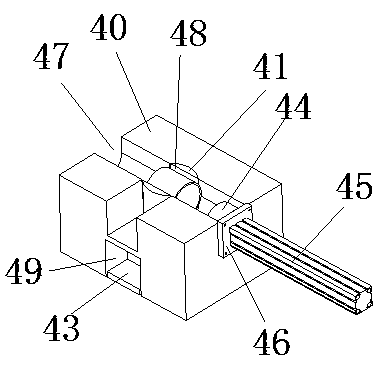
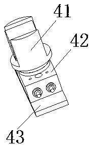
[0009] see figure 1 and figure 2 , the embodiment of the present invention includes:

[0010] A bushing unit separation mechanism for a bushing automatic recognition feeder, the bushing unit separation mechanism for a bushing automatic recognition feeder includes a separation body seat 40, a separation rotary mold 41, a turntable cylinder 42, and a turntable cylinder pad Plate 43, pusher die 44, pusher cylinder 45 and pusher cylinder flange 46, the circular hole in the middle of the separation body seat 40 is provided with a rotatable separation rotary die 41, the groove 48 of the separation rotary die 41 and the separation The "T" groove 47 of the bo...


PUM


Abstract

The invention discloses an individual bush separation mechanism of an automatic identifying bush loader. The individual bush separation mechanism of the automatic identifying bush loader comprises a separation body base, a rotary die for separation, a turret cylinder, a turret cylinder base plate, a pushing die, a pushing cylinder and a pushing cylinder flange; the rotatable rotary die for separation is arranged in a round hole formed in the middle of the separation body base; the groove of the rotary die for separation is communicated with the T-shaped groove of the separation body base; the lower end of the rotary die for separation is fixed on the turret of the turret cylinder; the turret cylinder is located in a through groove formed in the lower part of the separation body base and mounted on a machine table facet; the turret cylinder base plate is arranged between the turret cylinder and the machine table facet; the pushing die is arranged in the T-shaped groove of the separation body base and connected with the piston rod of the pushing cylinder; the pushing cylinder is fixed on the side surface of the separation body base by use of the pushing cylinder flange. The individual bush separation mechanism of the automatic identifying bush loader is capable of separating a bush to be welded independently instead of manual work.

Description

technical field [0001] The invention relates to the field of automation equipment, in particular to a bushing monomer separation mechanism of a bushing automatic recognition feeding machine. Background technique [0002] The bushing is a necessary wear-resistant product for some moving joints in the automation equipment. Its main purpose is to reduce the wear of the joint body of the equipment. Adjust the gap, but the precision bushing cannot have gaps. It needs to be welded to complete, but the existing processes are all manually discharged to the fixture and then completed by solder welding. During the welding process, manual feeding and welding are required. Sometimes the solder will melt and splash, producing solder slag, and there will be a certain amount of scrap during welding. Welding is done manually, so the efficiency is relatively low. Fully automatic welding machines need to be automatically loaded to complete, and the efficiency of manual identification of weld...

Claims


Application Information

Patent Timeline
IPC IPC(8): B23K37/00
CPCB23K37/00
Inventor 施建兰
Owner SUZHOU ISHIMARU ERI PML PRECISION MECHANISM CO LTD
Learn More