
Client distributed path computation method based on software defined network architecture

A software-defined network and path calculation technology, applied in data exchange networks, electrical components, digital transmission systems, etc., can solve problems such as uncontrollability, inconvenience, and low transparency of network protocols, so as to optimize resource use, change limitations, and improve The effect of transparency

Active Publication Date: 2014-12-31
SOUTH CHINA UNIV OF TECH
View PDF7 Cites 43 Cited by
  • Summary
  • Abstract
  • Description
  • Claims
  • Application Information

AI Technical Summary

Problems solved by technology

[0002] The traditional communication network relies on the OSI seven-layer network protocol stack to work. The control plane of the network is scattered in different devices, and the transparency of network protocol operation is low.
For users, how applications use the network protocol stack and information security cannot be intuitively grasped or controlled; for network managers, the network is like a black box, and it is difficult to control the traffic distribution in the network, which is not conducive to the maintenance and maintenance of network equipment. optimization; and for network operators, it is extremely inconvenient to update all network equipment every time they upgrade equipment or change the operation charging method
[0003] The shortcomings of traditional networks have been criticized for a long time. Although the emergence of elastic computing, virtual network technology, and MPLS has alleviated the shortcomings of traditional networks to a certain extent, it has greatly increased the complexity of the network and brought new challenges to network managers and researchers. At the same time, it also increases the difficulty and cost of network protocol upgrades and modifications

Method used


Image

  • Client distributed path computation method based on software defined network architecture
  • Client distributed path computation method based on software defined network architecture
  • Client distributed path computation method based on software defined network architecture

Examples


Embodiment Construction

[0027] The present invention will be further described in detail below in conjunction with the embodiments and the accompanying drawings, but the embodiments of the present invention are not limited thereto.

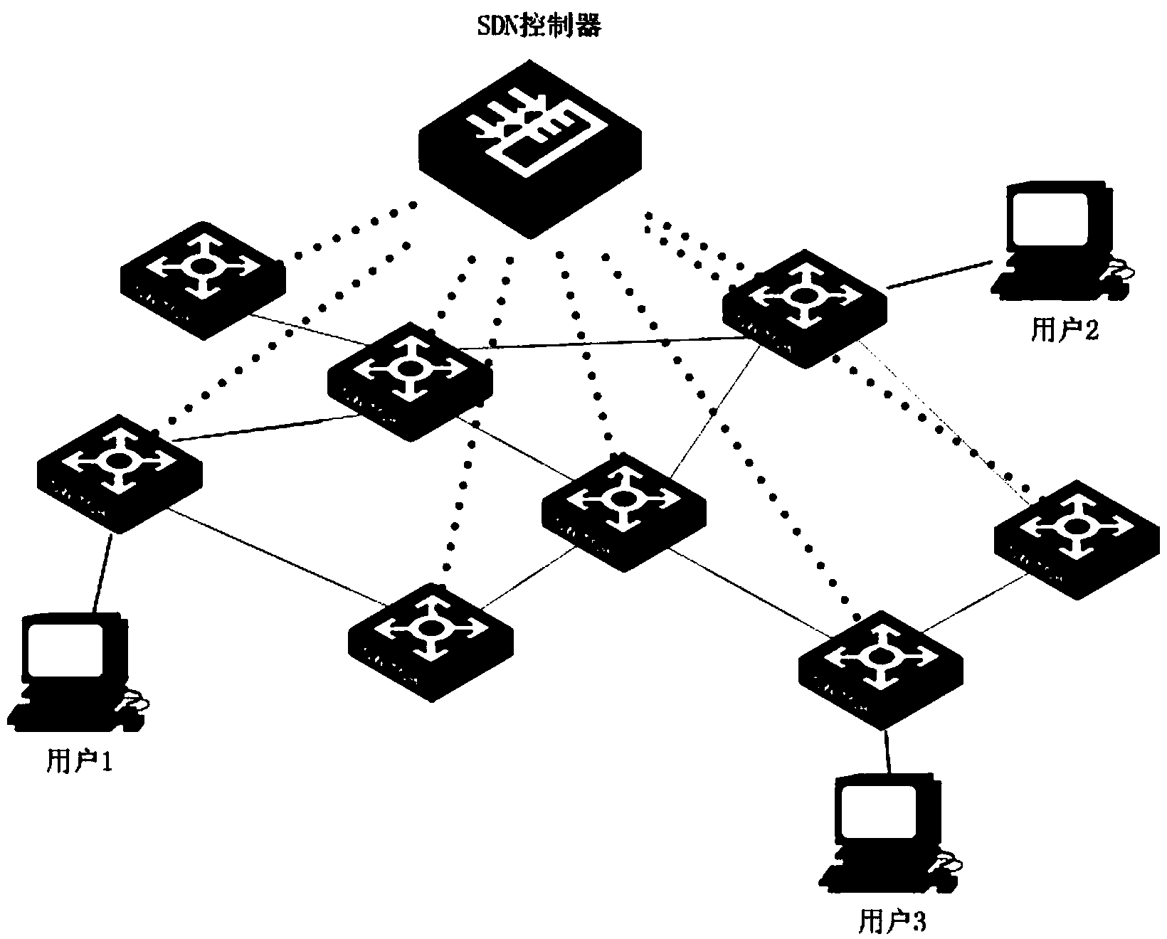
[0028] Such as figure 1 , a distributed path computation method based on a software-defined network architecture at a user end, comprising the following steps:

[0029] (1) Through the northbound interface of the software-defined network, the user interacts with the network controller and requests the network topology and link cost information from the network controller;

[0030] (2) Under the software-defined network architecture, the network controller communicates with the network switching / forwarding equipment through the southbound interface (such as the OpenFlow protocol), controls the forwarding of data in the network, and obtains the network topology and link information, including Bandwidth, delay, traffic, etc.;

[0031] The network controller periodically m...


PUM


Abstract

The invention discloses a client distributed path computation method based on a software defined network architecture. The client distributed path computation method comprises the following steps: a user obtains network topology and linkcost information from a network controller through a northbound interface of a controller, calculates the path on the basis, determines route and flow distribution, and submits a route request to the controller; the network controller is responsible for updating the network topology and link state, and issuing a flow statement to data forwarding equipment according to the route selection of the user. Through the route calculation, the user participates in the network control to achieve the distributed optimization during the use process of network resources; meanwhile, the controller provides network topology information for the user, and can achieve the virtualization of the network resources and functions for the user and the optimal configuration and the integrated use of the network resources. Through the application of the method, the user can get great rights within a network safety range, the network transparency is improved, and an SDN frame serves for the user.

Description

technical field [0001] The present invention relates to the fields of software-defined network, network control and management, and network path calculation, and in particular to a user-side distributed path calculation method based on software-defined network architecture. Background technique [0002] The traditional communication network relies on the OSI seven-layer network protocol stack to work, the control plane of the network is scattered in different devices, and the transparency of network protocol operation is low. For users, how applications use the network protocol stack and information security cannot be intuitively grasped or controlled; for network managers, the network is like a black box, and it is difficult to control the traffic distribution in the network, which is not conducive to the maintenance and maintenance of network equipment. optimization; and for network operators, it is extremely inconvenient to update all network equipment every time they upg...

Claims


Application Information

Patent Timeline
Patent Type & Authority Applications(China)
IPC IPC(8): H04L12/721
Inventor 官权升陈天宇陈晓菲王妍堃陈涵
Owner SOUTH CHINA UNIV OF TECH
Learn More