
Switching power supply circuit

A technology of switching power supply circuits and switching tubes, applied in electrical components, adjusting electrical variables, instruments, etc., can solve problems such as output voltage spikes, MOSFETs are easily damaged, and electrical appliances are damaged

Active Publication Date: 2014-12-31
ANYUAN XIAN MEIJING ELECTRONICS CO LTD
View PDF7 Cites 2 Cited by
  • Summary
  • Abstract
  • Description
  • Claims
  • Application Information

AI Technical Summary

Problems solved by technology

[0002] At present, in switching power supply circuits with higher voltage input, MOSFETs are easily damaged
In addition, when the power is turned on, the voltage at the output terminal is prone to spikes, or the temporary voltage exceeds the rated output voltage, and there is a risk of damage to the electrical appliances

Method used


Image

  • Switching power supply circuit
  • Switching power supply circuit

Examples


Embodiment Construction

[0015] The preferred embodiments of the invention will be further described in detail below.

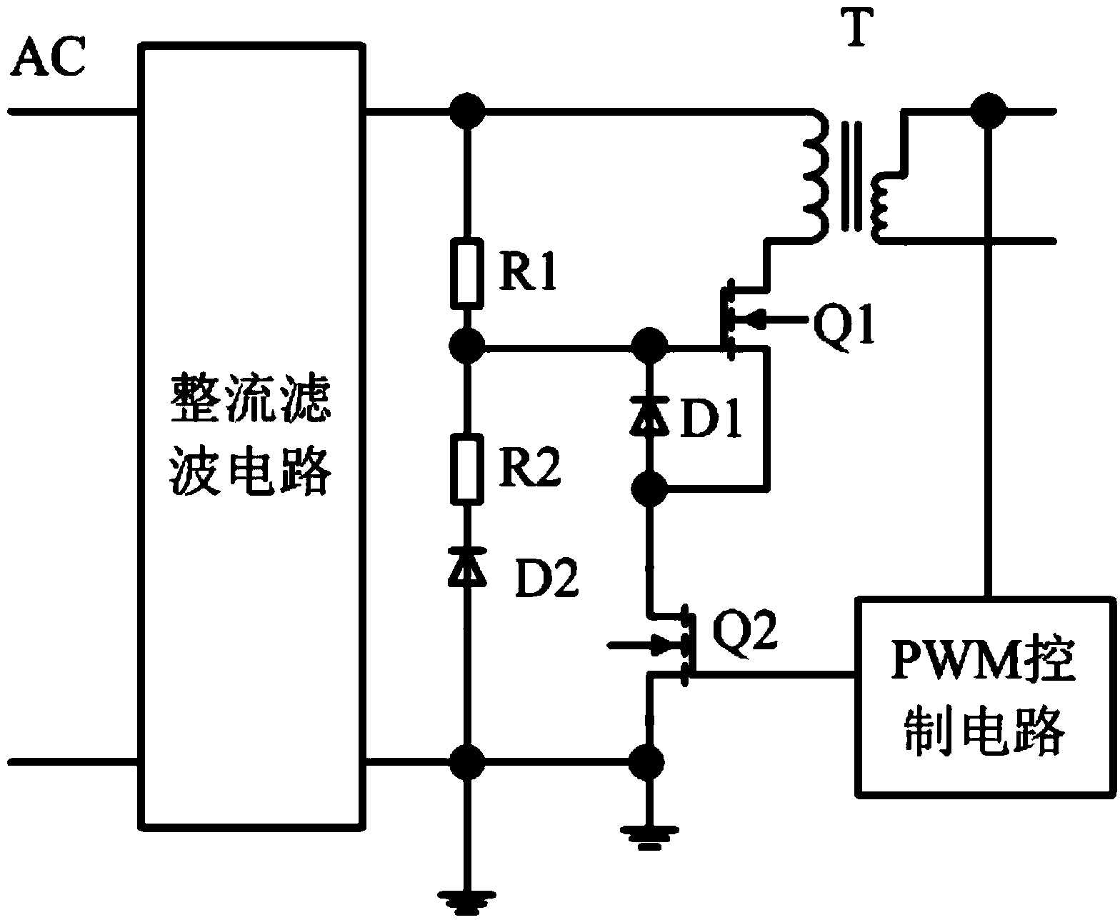
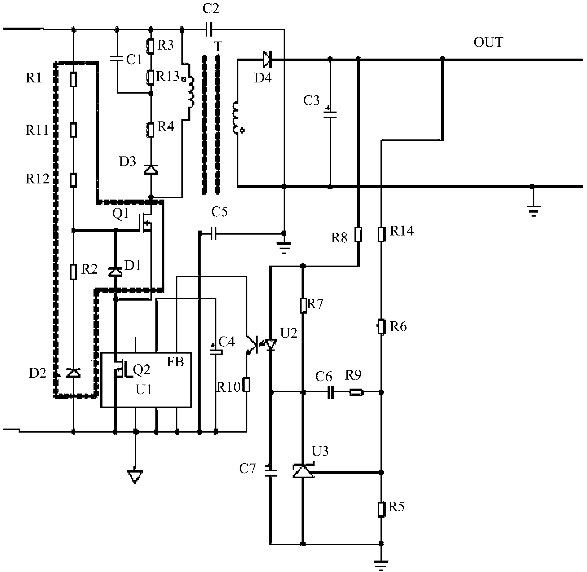
[0016] Such as figure 1 and 2 As shown, a switching power supply circuit of an embodiment includes a rectification filter circuit, a PWM control circuit, a transformer T, a first resistor R1, a second resistor R2, a first MOS switch Q1, a second MOS switch Q2, a first a diode D1 and a second diode D2, the first output terminal of the rectification filter circuit is connected to the cathode of the second diode D2 through the first resistor R1 and the second resistor R2 in turn, and the second The anode of the diode D2 is connected to the ground, the first end of the primary coil of the transformer T is connected to the first output end of the rectification filter circuit, and the second end of the primary coil of the transformer passes through the first MOS switch in turn The tube Q1 and the second MOS switch tube Q2 are connected to ground, the base of the first MOS switch tube Q1 ...


PUM


Abstract

The invention discloses a switching power supply circuit. The first output end of a rectifying and filtering circuit is successively connected with the cathode of a second diode via a first resistor and a second resistor; the anode of the second diode is connected with ground; the first end of the primary coil of a transformer is connected with the first output end of the rectifying and filtering circuit; the second end of the primary coil of a transformer is connected with the ground via a first MOS (metal oxide semiconductor) switching tube and a second MOS switching tube; the base electrode of the first MOS switching tube is connected with the common end of the second resistor; the cathode and the anode of a first diode are respectively connected with the base electrode and the source electrode of the first MOS switching tube; the input end and the output end of the circuit are controlled by PWM (Pulse-Width Modulation) to be respectively connected with the output end of the secondary coil of the transformer and the base electrode of the second MOS switching tube; the second output end of the rectifying and filtering circuit is connected with the ground.

Description

【Technical field】 [0001] The invention relates to a switching power supply circuit. 【Background technique】 [0002] At present, in switching power supply circuits with higher voltage input, MOSFETs are easily damaged. In addition, when the power is turned on, the voltage at the output terminal is prone to spikes, or the temporary voltage exceeds the rated output voltage, and there is a risk of damage to the electrical appliances. 【Content of invention】 [0003] In order to overcome the deficiencies of the prior art, the present invention provides a switching power supply circuit to reduce the probability of MOSFET being damaged; further, to reduce or reduce the peak voltage that occurs when starting up. [0004] A switching power supply circuit, including a rectification and filtering circuit, a PWM control circuit, and a transformer, and also includes a first resistor, a second resistor, a first MOS switch tube, a second MOS switch tube, a first diode, and a second diode...

Claims


Application Information

Patent Timeline
IPC IPC(8): H02M7/217H02M3/335
Inventor 石贤德肖铿
Owner ANYUAN XIAN MEIJING ELECTRONICS CO LTD
Learn More