
lens

A lens and lens barrel technology, applied in the lens field, can solve problems such as lens group deviation and lens imaging influence

Active Publication Date: 2016-09-07
QISDA OPTRONICS (SUZHOU) CO LTD +1
View PDF4 Cites 0 Cited by
  • Summary
  • Abstract
  • Description
  • Claims
  • Application Information

AI Technical Summary

Problems solved by technology

However, when the swivel ring is locked on the lens barrel with screws, it may cause the lens group in the lens barrel to deviate from the predetermined optical path due to the excessive locking force, which will affect the imaging of the lens

Method used


Image

  • lens
  • lens
  • lens

Examples


Embodiment Construction

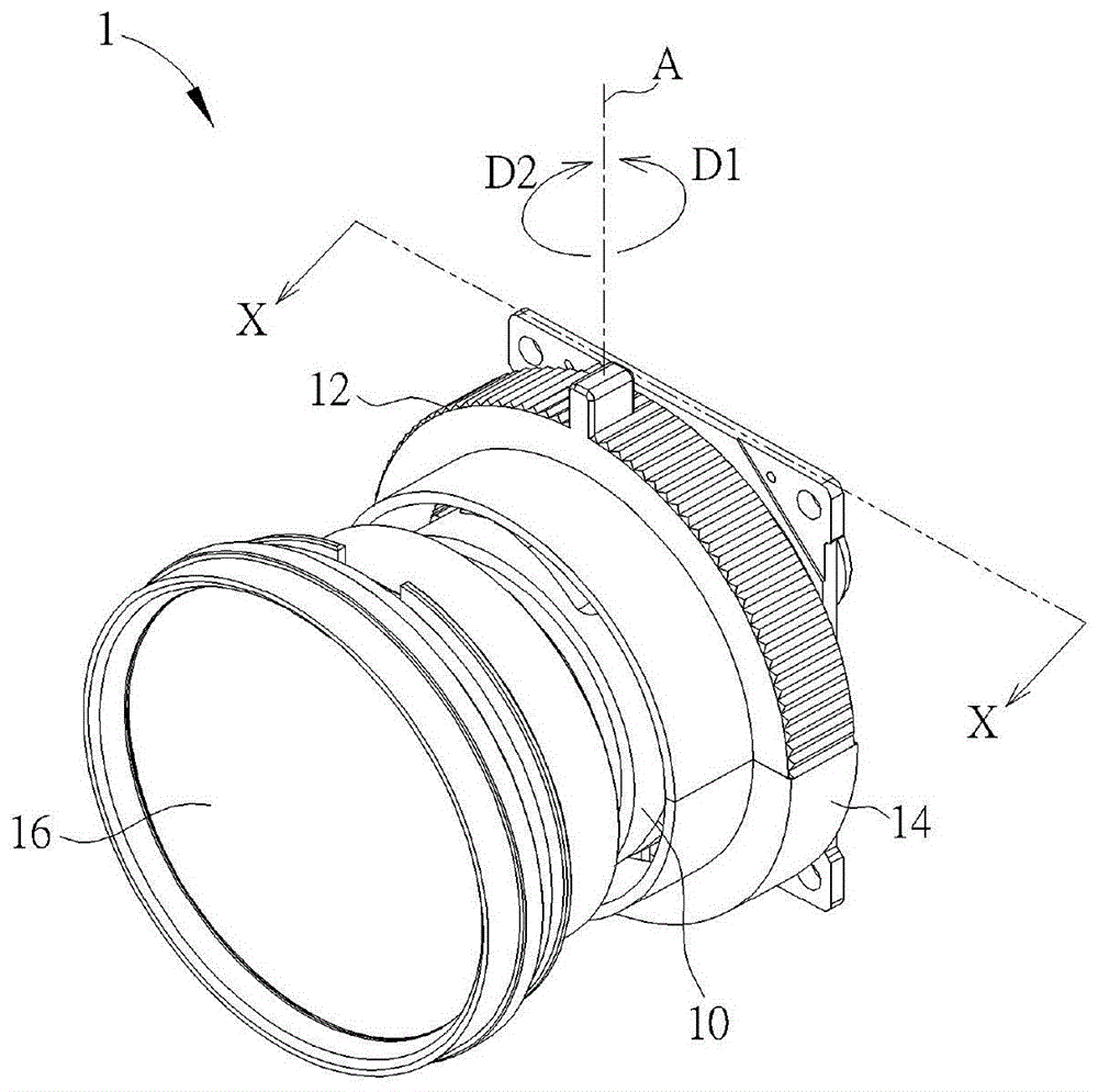
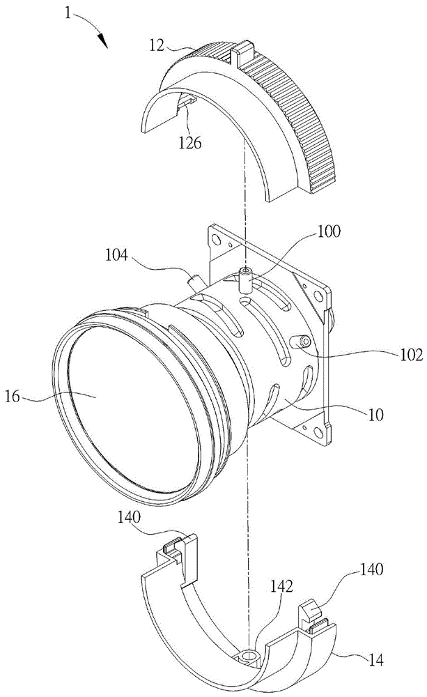
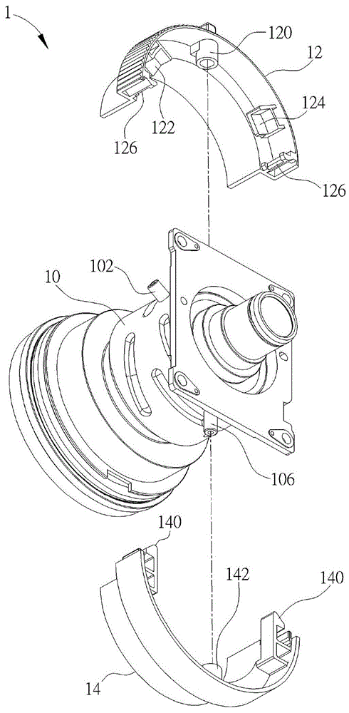
[0021] see Figure 1 to Figure 4 , figure 1 is a perspective view of a lens 1 according to an embodiment of the present invention, figure 2 for figure 1 Exploded view of lens 1 in, image 3 for figure 1 Exploded view of lens 1 in another perspective, Figure 4 for figure 1 The sectional view of the lens 1 along the line X-X in .

[0022] Such as Figure 1 to Figure 4 As shown, the lens 1 includes a lens barrel 10 , a first swivel 12 and a second swivel 14 . The lens 1 can be applied to cameras, projectors or other electronic devices with imaging functions, depending on the actual application. In practical applications, the lens barrel 10 is provided with a lens group 16 for imaging. The lens barrel 10 has a first positioning portion 100 , a first protruding portion 102 and a second protruding portion 104 , wherein the first protruding portion 102 and the second protruding portion 104 are located on two sides of the first positioning portion 100 . The first swivel 12...


PUM


Abstract

The invention provides a lens, which includes a lens barrel and a first swivel ring. The lens barrel has a first positioning part, a first protruding part and a second protruding part, wherein the first protruding part and the second protruding part are located at two sides of the first positioning part. The first swivel has a second positioning portion, a first retaining wall and a second retaining wall, wherein the first retaining wall and the second retaining wall are located at two sides of the second positioning portion. When the first swivel is set on the lens barrel, the first positioning portion and the second positioning portion are locked to each other, and the first retaining wall and the second retaining wall stop the first protruding portion and the second protruding portion against the first The axis of the positioning part rotates.

Description

technical field [0001] The invention relates to a lens, in particular to a lens in which a lens barrel and a swivel are assembled in a clamping manner. Background technique [0002] Lenses are indispensable components of cameras and projectors. Generally speaking, lenses can be divided into telescopic lenses (that is, zoom lenses) and fixed-focus lenses. The biggest difference between the two is the focal length value. The focal length value of a fixed focal length lens is a single value, while the focal length value of a telescoping lens is a range. Compared with the fixed-focus lens, the telescopic lens has an additional swivel ring for adjusting the focal length value. The user can turn the rotary ring to select the desired focal length. At present, the swivel ring on the lens is directly locked on the lens barrel with screws. However, when the swivel ring is locked on the lens barrel with screws, the lens group in the lens barrel may deviate from the predetermined opt...

Claims


Application Information

Patent Timeline
Patent Type & Authority Patents(China)
IPC IPC(8): G02B7/04
Inventor 柯延锋萧启宏何文中林颖芳
Owner QISDA OPTRONICS (SUZHOU) CO LTD
Learn More