
Light source

A light source and power supply technology, applied in the field of light sources, can solve the problems of long heat dissipation path, further improvement of heat dissipation effect, and easy formation of heat accumulation, etc.

Inactive Publication Date: 2014-12-31
OPPLE LIGHTING
View PDF5 Cites 5 Cited by
  • Summary
  • Abstract
  • Description
  • Claims
  • Application Information

AI Technical Summary

Problems solved by technology

The heat dissipation path of this structure is too long, it is easy to form heat accumulation, and the heat dissipation effect needs to be further improved

Method used


Image

  • Light source
  • Light source

Examples


Embodiment Construction

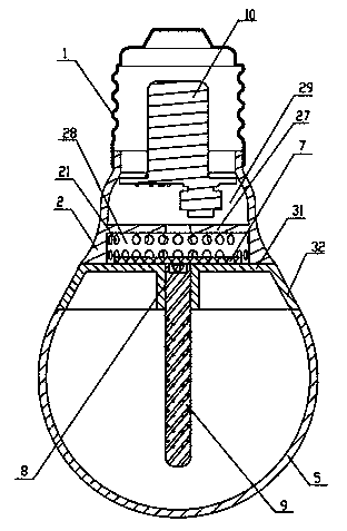
[0018] Below to Figures 1 to 2 The light source of the present invention will be described in detail by taking the LED bulb lamp in the present invention as an example. The LED bulb lamp of this embodiment includes a lamp body, a lampshade 5, a lamp cap 1, an LED 8 and a substrate 7, the lampshade 5 is connected to the lamp body, the lamp cap 1 is connected to the lamp body, and the LED 8 is arranged on On the substrate 7, the light of the LED 8 is emitted from the lampshade 5, the lamp body is provided with a cooling cavity 28 for accommodating the substrate 7, and the lamp body is provided with a position corresponding to the cooling cavity 28. The heat dissipation hole 21 communicates with the heat dissipation chamber 28 and the external space. By setting the heat dissipation chamber 28 and the heat dissipation hole 21, and placing the substrate 7 in the heat dissipation chamber 28, after the heat dissipated by the LED8 during operation is transferred to the substrate 7, ...


PUM


Abstract

The invention relates to a light source, which comprises a lamp body, a lamp shade, a lamp head, an LED (light emitting diode) and a substrate, wherein the lamp shade is connected with the lamp body, the lamp head is connected with the lamp body, the LED is arranged on the substrate, the light rays of the LED are emitted out of the lamp shade, the interior of the lamp body is provided with a heat radiating cavity for containing the substrate, the part, corresponding to the heat radiating cavity, of the lamp body is provided with heat radiating holes, and the heat radiating holes are used for communicating the heat radiating cavity with outside space. Compared with the prior art, the light source has better heat radiating effect.

Description

technical field [0001] The invention relates to the field of lighting, in particular to a light source. Background technique [0002] LED lighting products have many advantages such as environmental protection, energy saving, and long life, and have the tendency to gradually replace traditional incandescent lamps and fluorescent lamps as the main lighting products. However, due to the large amount of heat emitted by the LED during operation, if the design of the heat dissipation structure of the LED lighting product is not reasonable, its luminous efficiency and lifespan will be seriously affected. [0003] The substrate of the existing LED bulb lamp is placed inside the lampshade, and the heat emitted by the LED is first conducted downward from the substrate to the metal shell, and then dissipated into the air. The heat dissipation path of this structure is too long, it is easy to form heat accumulation, and the heat dissipation effect needs to be further improved. Cont...

Claims


Application Information

Patent Timeline
Patent Type & Authority Applications(China)
IPC IPC(8): F21S2/00F21V29/00F21Y101/02
Inventor 梁华星武俊张正华卞娟
Owner OPPLE LIGHTING
Learn More