Optically pumped vertical external-cavity surface-emitting laser device

A surface-emitting laser and surface-emitting technology, applied in the structure of optical resonators, optics, lasers, etc., can solve the problems of huge modules, time-consuming production, etc., and achieve the effect of good efficiency and compact design

Active Publication Date: 2014-12-24
KONINKLIJKE PHILIPS NV
View PDF6 Cites 3 Cited by
  • Summary
  • Abstract
  • Description
  • Claims
  • Application Information

AI Technical Summary

Problems solved by technology

This requires time-consuming production and bulky modules

Method used


Image

  • Optically pumped vertical external-cavity surface-emitting laser device
  • Optically pumped vertical external-cavity surface-emitting laser device
  • Optically pumped vertical external-cavity surface-emitting laser device

Examples


Embodiment Construction

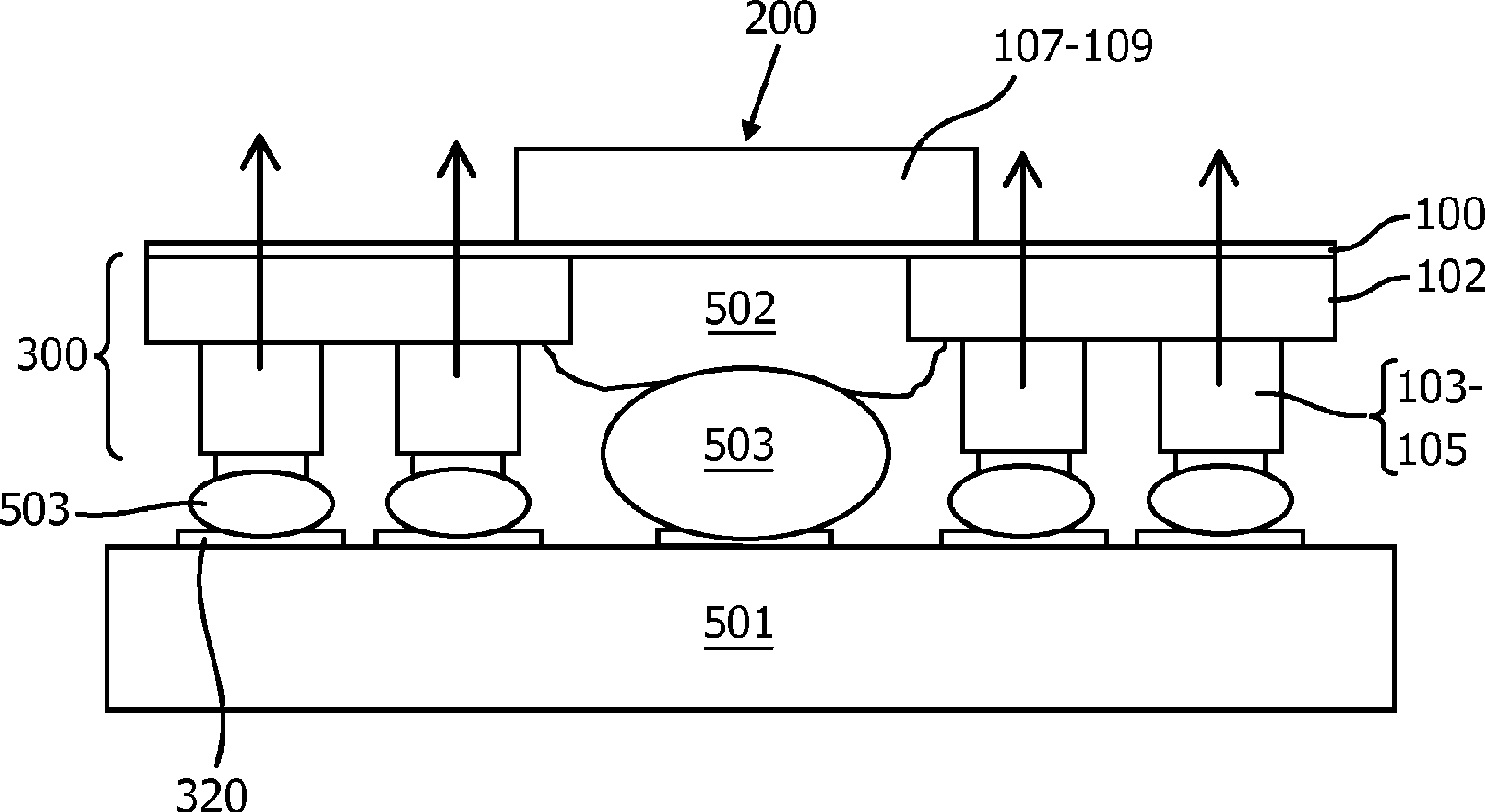
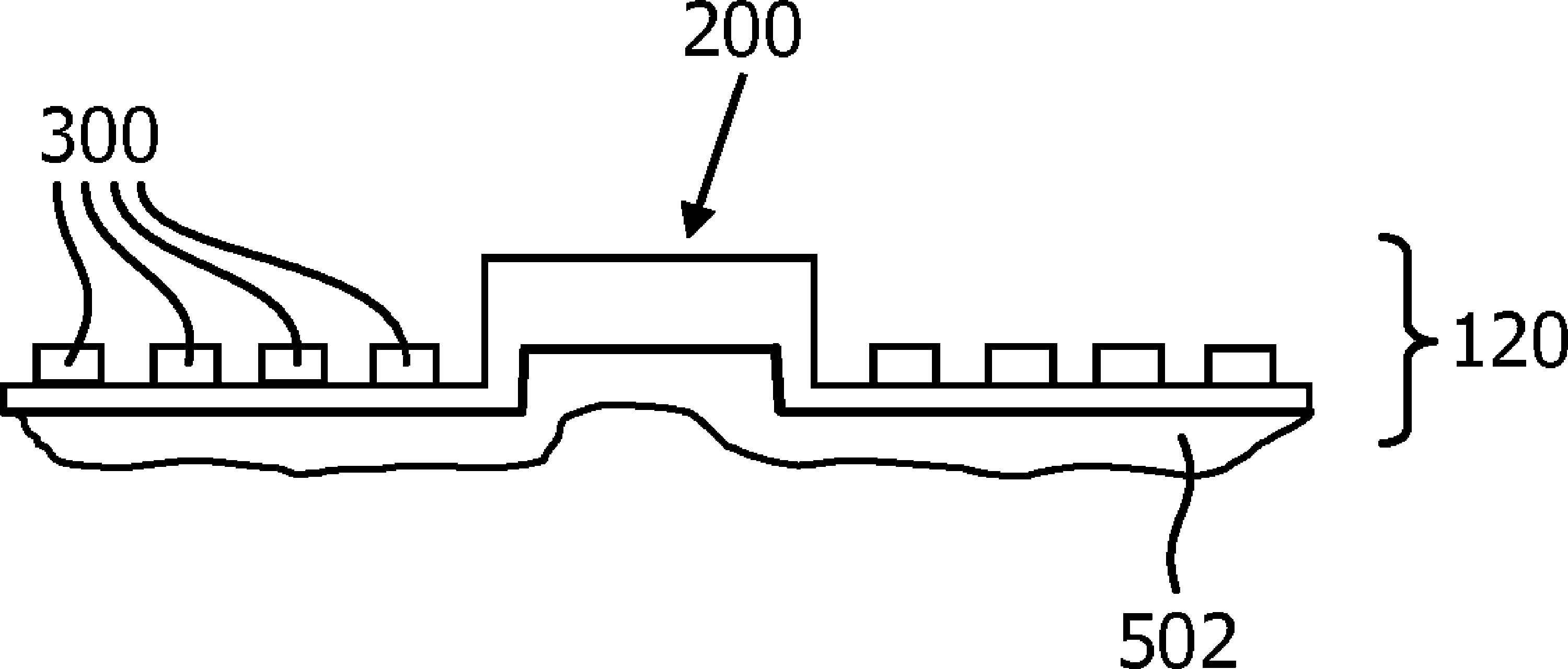
[0025] Figure 1-3 A first example of the proposed laser device and its fabrication is shown. In this example, the pump laser diode is VCSEL 300 integrated on the same chip 120 as VECSEL 200 . VCSEL 300 is arranged to surround VECSEL 200 . In this embodiment, all semiconductor lasers are as figure 1 The top-emitting laser shown in . A mirror element 400 (free-form optics) comprising at least two radial mirror regions 410 , 420 is arranged in front of the semiconductor chip 120 . In this embodiment, the mirror element 400 is formed by an optically transparent body comprising a first surface 401 facing the semiconductor chip 120 and a second surface 402 . The first surface 401 is coated so as to provide sufficient reflectivity (R(λ) for laser operation of the VECSEL 200 VECSEL ) = 80 – 99,5%) and the highest possible reflection of the pump light of the VCSEL 300 (R(λ VCSEL ) > 95%, preferably > 99%). The surface 401 is divided into two regions with different shapes.

[0...


PUM


Abstract

The present invention relates to an optically pumped vertical external-cavity surface-emitting laser device comprising at least one VECSEL (200) and several pump laser diodes (300). The pump laser diodes (300) are arranged to optically pump the active region (108) of the VECSEL (200) by reflection of pump radiation (310) at a mirror element (400). The mirror element (400) is arranged on the optical axis (210) of the VECSEL (200) and is designed to concentrate the pump radiation (310) in the active region (108) and to form at the same time the external mirror of the VECSEL (200). The proposed device avoids time consuming adjustment of the pump lasers relative to the active region of the VECSEL and allows a very compact design of the laser device.

Description

technical field [0001] The present invention relates to an optically pumped vertical external cavity surface emitting laser device comprising at least one vertical external cavity surface emitting laser (VECSEL) and several pump laser diodes, wherein the pump laser diodes are arranged to pass through a mirror The active region of the VECSEL is optically pumped by reflecting the pump radiation at the element. Vertical external-cavity surface-emitting lasers are one of the most promising high-brightness laser sources and offer many advantages over edge emitters, such as addressable 2D array arrangements and circular beam shapes. Background technique [0002] A VECSEL typically comprises an active region formed in a layer sequence and a first end mirror and a second end mirror arranged separate from the layer sequence and forming the outer cavity of the laser. In a standard setup, the external cavity consists of macroscopic optics that are very bulky and require related adjust...

Claims


Application Information

Patent Timeline
Patent Type & Authority Applications(China)
IPC IPC(8): H01S5/04H01S5/14H01S5/42H01S3/08H01S5/022H01S5/024H01S5/026H01S5/183H01S5/00
CPCG02B17/06H01S3/08068H01S5/0071H01S5/02476H01S5/026H01S5/041H01S5/141H01S5/18305H01S5/18388H01S5/423H01S5/02326H01S5/18397
Inventor S. 格罗恩博尔恩M. 米勒
Owner KONINKLIJKE PHILIPS NV
Why Eureka
Try Eureka