Series Multi-terminal DC Transmission System

A power transmission system, multi-terminal DC technology, applied in the direction of DC network circuit devices, electrical components, circuit devices, etc., can solve problems such as indistinguishability

Active Publication Date: 2016-11-02
HITACHI ENERGY SWITZERLAND AG
View PDF5 Cites 0 Cited by
  • Summary
  • Abstract
  • Description
  • Claims
  • Application Information

AI Technical Summary

Problems solved by technology

In this way, when this kind of fault occurs, for the protection of 400kv line, the traveling wave during the fault has a voltage change rate similar to that of the external fault and a higher amplitude, so it cannot be distinguished from the fault on the 400kV line

Method used


Image

  • Series Multi-terminal DC Transmission System
  • Series Multi-terminal DC Transmission System
  • Series Multi-terminal DC Transmission System

Examples


Embodiment Construction

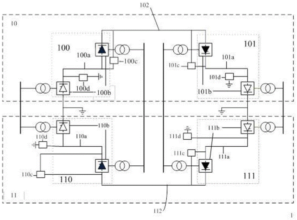
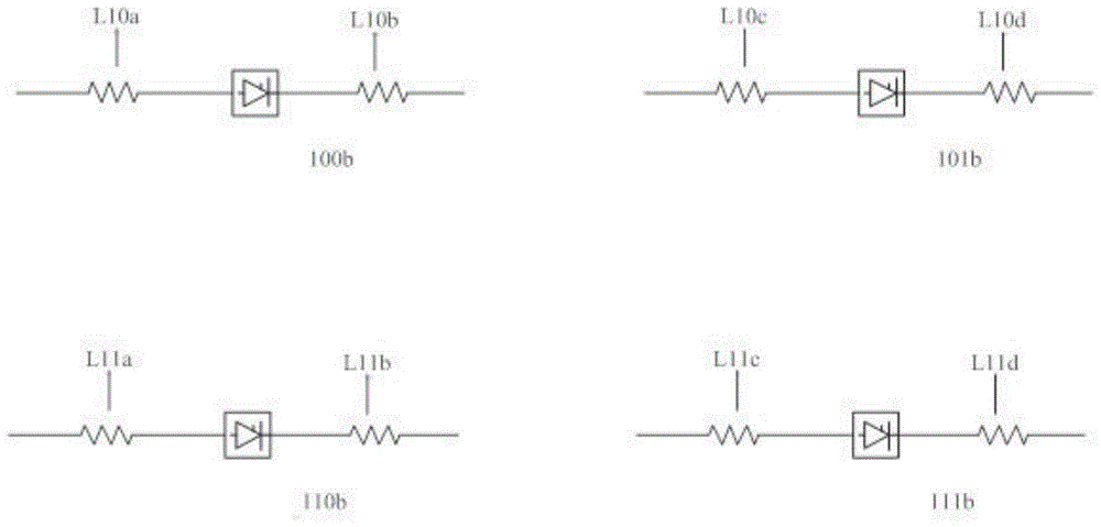
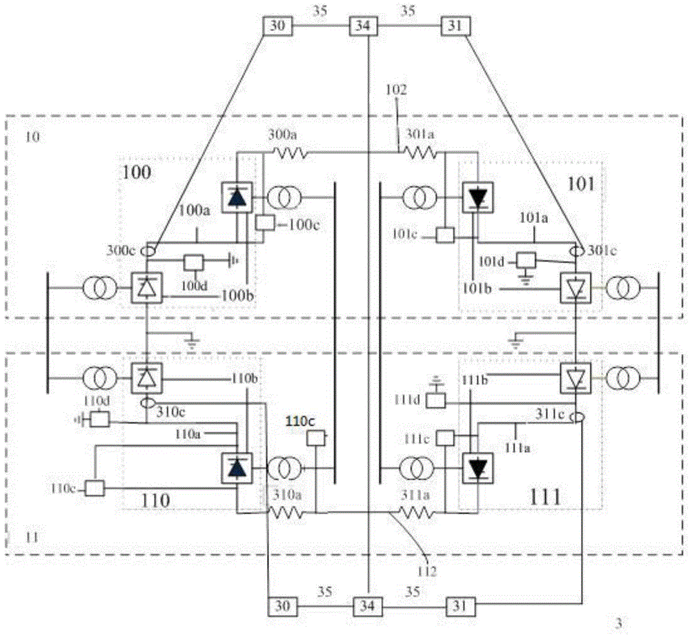
[0015] image 3 A bipolar multi-terminal direct current transmission system according to an embodiment of the present invention is shown. image 3 The shown bipolar multi-terminal direct current transmission system 3 and figure 1The difference of the bipolar multi-terminal direct current transmission system 1 shown is that for at least one converter unit 100b, 101b, 110b, 111b on the high voltage side (the shaded one in the same group of converter units represents the transformation of the high voltage side Converter unit) is improved, and a filter is arranged between the first DC terminal of the first converter unit group in the converter unit group and the high-voltage DC pole line outside the area, which is used for the high-voltage direct current from the outside area. AC filtering is performed for the fault component signal of the pole line and DC filtering is performed for the output signal from the converter cell bank. For example, at the first DC terminal of the firs...


PUM


Abstract

The invention provides a series multi-terminal direct current transmission system, comprising: a converter unit group, which are respectively a rectifier unit group and an inverter unit group; and an external high-voltage direct current pole line. The rectifier unit group includes at least two converter units connected in series through at least one DC bus in the zone; the inverter unit group includes at least two converter units connected in series through at least one DC bus in the zone; the first of the rectifier unit group The DC terminal and the first DC terminal of the inverter unit group are respectively electrically coupled with the first terminal and the second terminal of the high-voltage DC pole line outside the area; the second DC terminal of the rectifier unit group and the first terminal of the inverter unit group The two DC terminals are respectively electrically coupled to the first grounding pole and the second grounding pole; the filter is located between the first DC terminal of the first converter unit group in the converter unit group and the external high-voltage DC pole line. By adopting the above topology, it is possible to distinguish faults outside the zone from faults inside the zone.

Description

technical field [0001] The present invention relates to a multi-terminal direct current transmission system, more specifically, to a series multi-terminal direct current transmission system. Background technique [0002] With the development of power electronics technology, DC power grid has become a development trend, including series multi-terminal DC transmission system and parallel multi-terminal DC transmission system. Among them, the series multi-terminal DC transmission system has the advantages of low construction cost and large transmission capacity. [0003] figure 1 An existing bipolar multi-terminal DC transmission system is shown. Such as figure 1 As shown, the bipolar multi-terminal direct current transmission system 1 includes a positive multi-terminal direct current transmission system 10 and a negative multi-terminal direct current transmission system 11 . The positive multi-terminal DC power transmission system 10 includes two sets of converter units, w...

Claims


Application Information

Patent Timeline
Patent Type & Authority Patents(China)
IPC IPC(8): H02J1/00H02J3/36G01R31/08
CPCY02E60/60
Inventor 刘凯李幼仪王建平王庆平杨晓波
Owner HITACHI ENERGY SWITZERLAND AG
Why Eureka
Try Eureka