Data line material processing tooling

A material processing and data line technology, applied in the field of connector cable processing equipment, can solve problems such as slow welding speed, high manual labor intensity, and old welding methods, and achieve good product quality, high production efficiency, and labor-saving effects.

Active Publication Date: 2016-08-24
江苏双春电子科技有限公司
View PDF5 Cites 0 Cited by
  • Summary
  • Abstract
  • Description
  • Claims
  • Application Information

AI Technical Summary

Problems solved by technology

[0002] With the rapid growth of consumer electronics, automotive electronics, and communication terminal markets, communication cables are widely used in all aspects of daily life. Under the current background of industrial upgrading, there are two main production methods for cables or data lines: 1. Manual welding, that is, the combination of the connector and the cable or data line and the welding and fixing are all realized manually. The disadvantage of this production method is that the labor intensity is high, the connector is prone to over-welding or lack of welding, and the quality of the connector is not good. Stable; 2. Machine welding, that is, the connector and the cable or data line are combined by a machine, and are welded by manual welding or by a machine using an electric soldering iron. The disadvantage of this implementation is that the welding method is old and the welding speed is slow, which cannot meet large The need for batch modern production

Method used


Image

  • Data line material processing tooling
  • Data line material processing tooling
  • Data line material processing tooling

Examples


Embodiment Construction

[0017] The preferred embodiments of the present invention will be described in detail below in conjunction with the accompanying drawings, so that the advantages and features of the present invention can be more easily understood by those skilled in the art, so as to define the protection scope of the present invention more clearly.

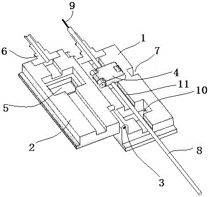
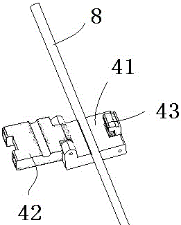
[0018] See attached figure 1 to attach figure 2 , the data line material processing tool in this embodiment includes a lower cover 1 and an upper cover 2 that are pivotally mounted together through a rotating shaft 3 , and a gap 7 for separating the two is provided on the lower cover 1 or the upper cover 2 . Between the lower cover 1 and the upper cover 2 is formed a cable channel 11 extending along the direction of the rotating shaft. One end of the cable channel 11 is provided with a cable clamping mouth 6. When the lower cover 1 and the upper cover 2 are pivoted open, The cable channel 11 and the cable clamping mouth 6 are cut longitudinally...


PUM


Abstract

The invention discloses a data line material processing tool capable of realizing precise positioning and fully automatic pick-and-place process, which comprises a lower cover and an upper cover which are pivotally installed together, and a shaft extending along the rotation axis direction is formed between the lower cover and the upper cover. Cable channel, at least one end of the cable channel is provided with a cable clamping mouth, when the lower cover and the upper cover are pivotally opened, the cable channel and the cable clamping mouth are longitudinally cut and distributed on both sides so that The cable is installed into the cable channel and exposed from the cable clamping mouth. The cable channel is also provided with an axial fixing clip. The axial fixing clip is located near the cable clamping mouth. The axial fixing clip includes a buckle The lower flap and the upper flap locked together, when the lower cover and the upper cover are pivotally closed, the upper flap and buckle are exposed through the opening in the lower cover or the upper cover.

Description

technical field [0001] The invention relates to a connector cable processing equipment. Background technique [0002] With the rapid growth of consumer electronics, automotive electronics, and communication terminal markets, communication cables are widely used in all aspects of daily life. Under the current background of industrial upgrading, there are two main production methods for cables or data lines: 1. Manual welding, that is, the combination of the connector and the cable or data line and the welding and fixing are all realized manually. The disadvantage of this production method is that the labor intensity is high, the connector is prone to over-welding or lack of welding, and the quality of the connector is not good. Stable; 2. Machine welding, that is, the connector and the cable or data line are combined by a machine, and are welded by manual welding or by a machine using an electric soldering iron. The disadvantage of this implementation is that the welding meth...

Claims


Application Information

Patent Timeline
Patent Type & Authority Patents(China)
IPC IPC(8): H01R43/20
Inventor 何源
Owner 江苏双春电子科技有限公司
Why Eureka
Try Eureka