
Single-phase electronic type keyboard prepayment meter

A prepaid electric energy meter, an electronic technology, applied in the field of instrumentation and electrical instruments, can solve the problems of power failure of the keyboard prepaid electric energy meter, the card slot being easily damaged, and not being disclosed.

Active Publication Date: 2014-12-24
ZHEJIANG CHINT INSTR & METER
View PDF4 Cites 9 Cited by
  • Summary
  • Abstract
  • Description
  • Claims
  • Application Information

AI Technical Summary

Problems solved by technology

[0002] At present, the prepaid energy meters used in the market use various technologies to achieve the purpose of recharging and paying fees, such as contact IC card recharging, non-contact radio frequency card recharging, and remote communication recharging. The above recharging methods have their own disadvantages: contact IC card recharging needs Only by inserting the IC card into the card slot can the charging service be realized. However, the card slot of the contact IC card is easily damaged and cannot be recharged; the recharge of the non-contact radio frequency card only needs to put the radio frequency card within the radio frequency range to realize the recharge service , although the non-contact radio frequency card does not need to insert the radio frequency card into the card slot, but the non-contact radio frequency card is easily affected by the surrounding electromagnetic interference, which will cause card reading errors and affect the use; remote communication recharge realizes the recharge service through remote communication, although this method It avoids the disadvantages that the card slot is easy to be viciously damaged and is subject to surrounding electromagnetic interference. However, data transmission may be wrong during communication. The stability and reliability of this method need to be improved urgently
However, how the keyboard prepaid energy meter detects the power failure of the keyboard prepaid energy meter has not yet been made public.

Method used


Image

  • Single-phase electronic type keyboard prepayment meter
  • Single-phase electronic type keyboard prepayment meter
  • Single-phase electronic type keyboard prepayment meter

Examples


Embodiment 1

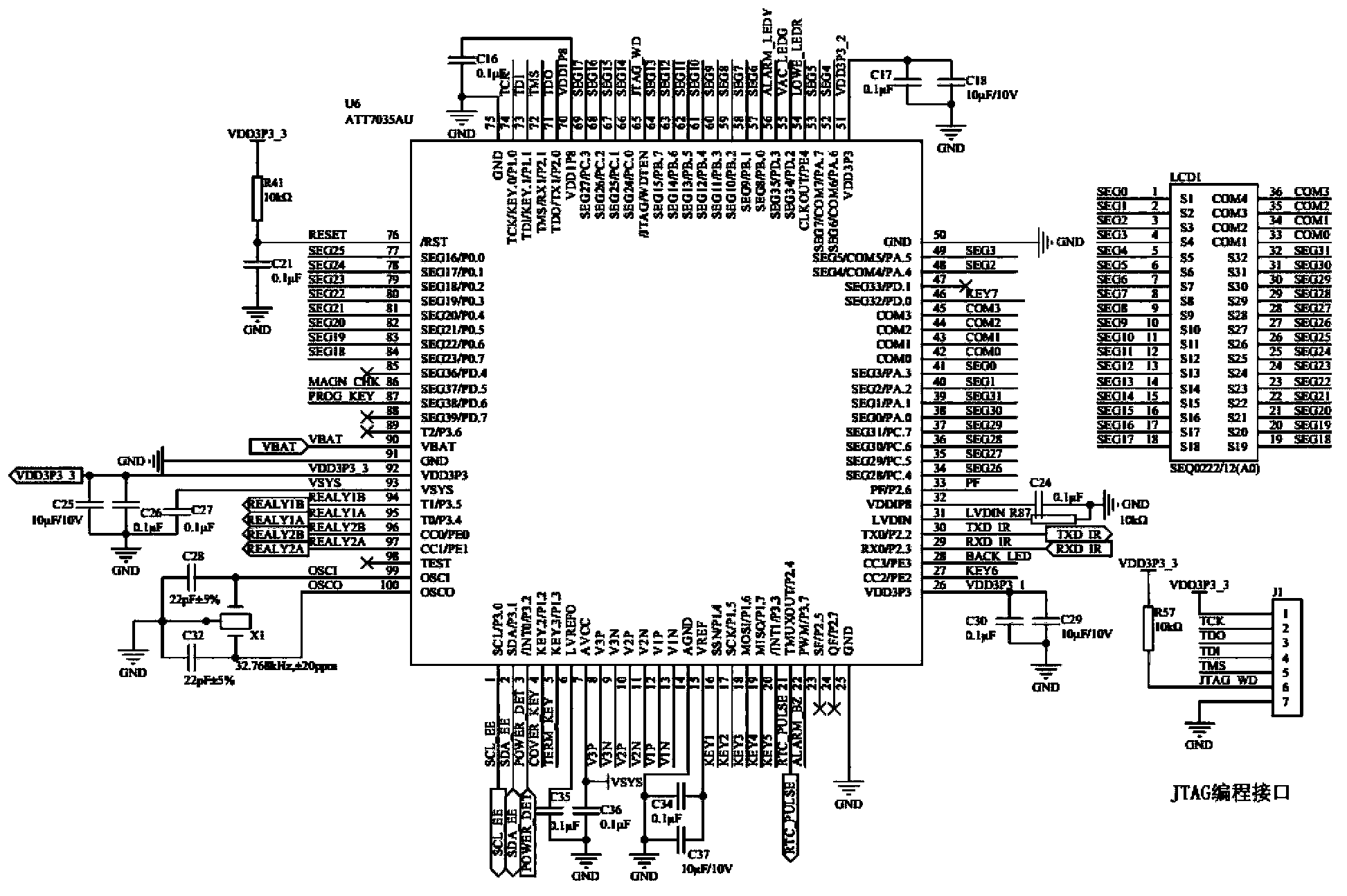
[0057] The structure of the single-phase electronic keyboard prepaid watt-hour meter circuit of the present invention is as follows: figure 1 As shown, it includes a SOC interface circuit 1, a power supply circuit 2 and a power-down detection circuit 3, wherein the power supply circuit 2 includes an output terminal that provides direct current to the outside; the SOC interface circuit 1 includes a control terminal, when the control terminal receives When the signal is turned on, the SOC interface circuit 1 operates normally; when the control terminal receives an interrupt signal, the SOC interface circuit 1 performs a power-down data storage action; the power-down detection circuit 3 includes an input terminal and An output terminal, the input terminal of the power failure detection circuit 3 is connected to the output terminal of the power supply circuit 2, and is used to receive the direct current provided by the power supply circuit 2; the output terminal of the power failur...

Embodiment 2

[0067] On the basis of the above embodiments, a relay control circuit is also included, the relay control circuit includes an L-phase relay control circuit and an N-phase relay control circuit; the L-phase relay control circuit and the N-phase relay control circuit have the same structure, see Figure 6 As shown, the L-phase relay control circuit and the N-phase relay control circuit both include triodes V4, V5, V8, V9, V12, V13, resistors R7, R8, R11, R12, R15, R16, R19, R20, R23, R24, R27, R28 and diodes D6, D7, D10, D11 and magnetic latching relay;

[0068] One end of the resistor R15 is connected to one end of the resistor R19 and their connection point is connected to the base of the triode V9, the other end of the resistor R15 is connected to the 95 pin of the ATT7035AU, and the other end of the resistor R19 is One end is simultaneously connected to the 94 pin of the ATT7035AU, the emitter of the triode V9 and one end of the resistor R23, and the other end of the res...

Embodiment 3

[0072] On the basis of Embodiments 1 and 2, a communication circuit is also included, and the communication circuit is a magnetic adsorption infrared communication circuit, see Figure 7 As shown, the magnetic adsorption infrared communication circuit includes a receiving circuit and a transmitting circuit, the receiving circuit includes resistors R31, R36, R38, R40, a triode V16 and an infrared receiving tube D14, and the transmitting circuit includes resistors R32, R37 , R39 and triode tube V17 and infrared emission tube D15.

[0073] The negative pole of the infrared receiving tube D14 is connected to one end of the resistor R31 and their connection point is connected to the Vout pin of the voltage regulator XC6214P332PR, the positive pole of the infrared receiving tube D14, one end of the resistor R38 are connected to the One end of the resistor R36 is connected, the other end of the resistor R36 is connected to the base of the transistor V16, the collector of the transist...


PUM


Abstract

The invention discloses a single-phase electronic type keyboard prepayment meter which comprises an SOC interface circuit, a power supply circuit and a power failure detection circuit. The power failure detection circuit detects a direct current power source output by the power supply circuit. When the situation that the voltage of the direct current output by power supply circuit is larger than or equal to a preset voltage threshold valve is detected by the power failure detection circuit, the power failure detection circuit outputs a connecting signal to the SOC interface circuit, the SOC interface circuit operates normally. When the situation that the voltage of the direct current output by power supply circuit is smaller than or equal to the preset voltage threshold valve is detected by the power failure detection circuit, the power failure detection circuit outputs an interrupt signal to the SOC interface circuit, and the SOC interface circuit executes power failure data storage action. According to the single-phase electronic type keyboard prepayment meter, the power failure detection circuit can accurately detect the magnitude of the direct current output by the power supply circuit, and the reliability of the operation of the single-phase electronic type keyboard prepayment meter is guaranteed.

Description

technical field [0001] The invention relates to an instrument, in particular to a single-phase electronic keyboard prepaid electric energy meter, which belongs to the technical field of electrical instruments. Background technique [0002] At present, the prepaid energy meters used in the market use various technologies to achieve the purpose of recharging and paying fees, such as contact IC card recharging, non-contact radio frequency card recharging, and remote communication recharging. The above recharging methods have their own disadvantages: contact IC card recharging needs Only by inserting the IC card into the card slot can the charging service be realized. However, the card slot of the contact IC card is easily damaged and cannot be recharged; the recharge of the non-contact radio frequency card only needs to put the radio frequency card within the radio frequency range to realize the recharge service , although the non-contact radio frequency card does not need to i...

Claims


Application Information

Patent Timeline
Patent Type & Authority Applications(China)
IPC IPC(8): G01R22/06
Inventor 李春章郭永娟
Owner ZHEJIANG CHINT INSTR & METER
Learn More