
Intelligent magnetic induction flux sensor

A flow sensor and electromagnetic induction technology, applied in the field of flow sensors, can solve problems such as long signal transmission distance, complex interface, and susceptibility to interference, and achieve the effects of high circuit reliability, simplified measurement system, and strong anti-interference ability

Active Publication Date: 2014-12-24
四川泛华航空仪表电器有限公司
View PDF5 Cites 5 Cited by
  • Summary
  • Abstract
  • Description
  • Claims
  • Application Information

AI Technical Summary

Problems solved by technology

[0004] The purpose of the present invention is to provide a small size, low power consumption, strong compatibility, reliability and other shortcomings in the existing technology consumption measurement system, which has many equipment involved, complex interface, long signal transmission distance, and easy to be interfered. Flow sensor with high performance, good versatility, and digital output signal

Method used


Image

  • Intelligent magnetic induction flux sensor
  • Intelligent magnetic induction flux sensor
  • Intelligent magnetic induction flux sensor

Examples


Embodiment Construction

[0015] The present invention will be further illustrated in the following examples, which are only used to illustrate the present invention and not to limit the present invention.

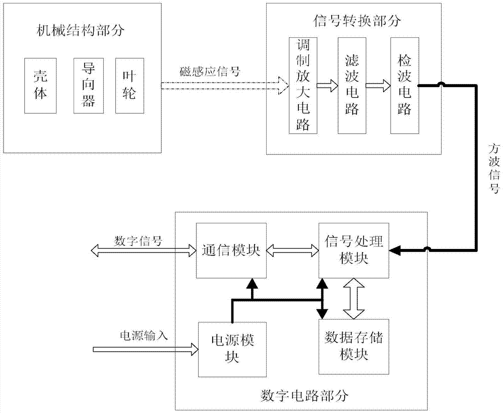
[0016] exist figure 1 Among them, the intelligent electromagnetic induction flow sensor includes a mechanical part, a signal conversion part and a digital part. The mechanical part includes impellers and guides that are assembled in the housing to generate electromagnetic induction signals. The signal conversion part and the digital part include a signal conversion circuit composed of a modulation amplifier circuit, a filter circuit and a detection and shaping circuit signal, and a digital circuit including a power supply module, a signal processing module, a data storage module and a communication module. The signal conversion circuit and digital circuit are made into a standard module and integrated in the flow sensor. The liquid flows through the flow sensor, drives the impeller to rotate throu...


PUM


Abstract

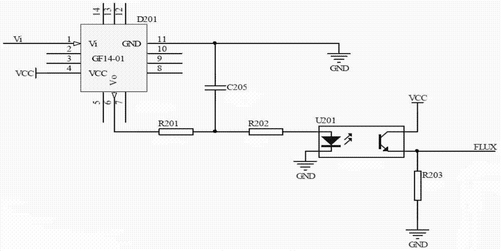
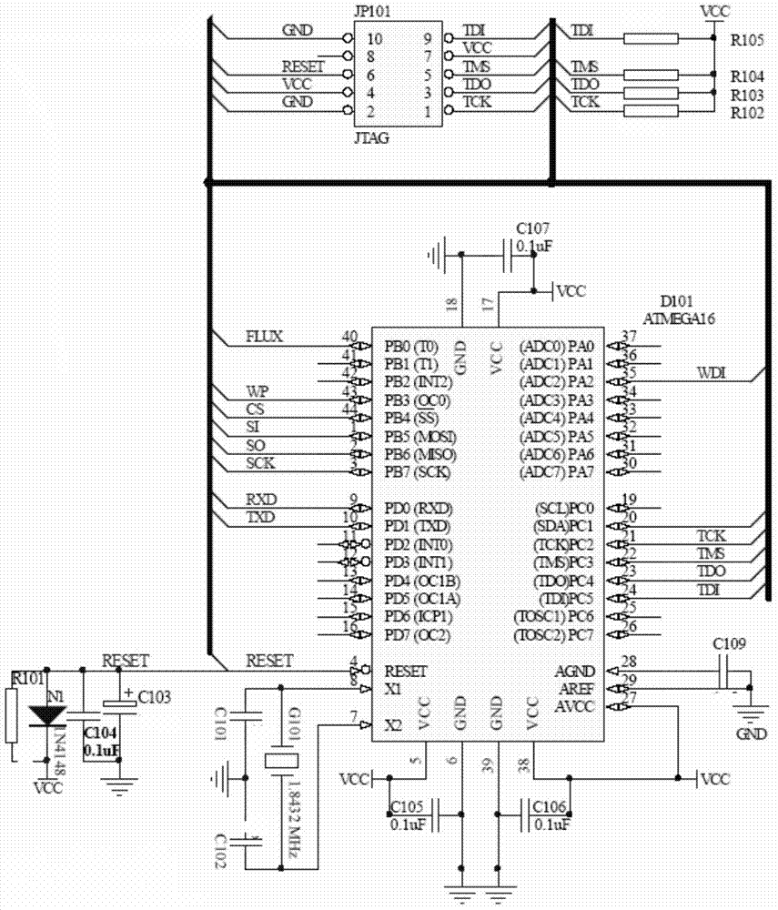
The invention provides an intelligent magnetic induction flux sensor which is low in power dissipation, high in compatibility and good in universality, and output signals are digital signals. According to the technical scheme, liquid flows through the flux sensor, an impeller is driven to rotate through a guider, voltage in direct proportion to average flux speed is sensed, electromagnetic induction voltage signals are transmitted to a converting processing circuit, square signals with the frequency and the flux in direct proportion are obtained by converting, a modulation amplifying circuit amplifies weak electromagnetic induction signals in a modulation mode, square signals with the duty ratio of 50% are obtained by converting, high-frequency parts in the signals are filtered out through an RC low-pass filtering circuit, a detector circuit shapes the square signals and sends the square signals to a signal processing module which computes collected signals, computing results are sent to a communication module and a data storage module, and by processing and computing of a signal data processor, flux information is sent to terminal equipment through the communication module.

Description

technical field [0001] The invention relates to a flow sensor which is mainly used for measuring fuel consumption and instantaneous flow of engines of airplanes, automobiles and ships, and can also be used for measuring pipeline liquid flow. Background technique [0002] Flow measurement plays a pivotal role in industry, agriculture and people's daily life, and flow sensors are widely used as flow measuring instruments. The turbine flow sensor converts the volume flow of the liquid flowing through the pipeline into a linear electrical signal. Its conversion principle is the famous Faraday's law of electromagnetic induction, that is, the fluid drives the impeller to cut the electromagnetic wire to generate electromotive force. The magnetic field of the flow sensor is realized by excitation, which is divided into DC excitation, AC excitation and low frequency square wave excitation. Most flow sensors now use low frequency square wave excitation. The transmitter is composed ...

Claims


Application Information

Patent Timeline
Patent Type & Authority Applications(China)
IPC IPC(8): G01F1/58
Inventor 张志明
Owner 四川泛华航空仪表电器有限公司
Learn More