Heat exchanger
A technology of heat exchangers and heat exchange plates, applied in the direction of heat exchanger types, indirect heat exchangers, heat storage equipment, etc., can solve problems such as inability to achieve heat exchange effects, and achieve the effect of ensuring heat exchange efficiency
- Summary
- Abstract
- Description
- Claims
- Application Information
AI Technical Summary
Problems solved by technology
Method used
Image
Examples
Embodiment 1
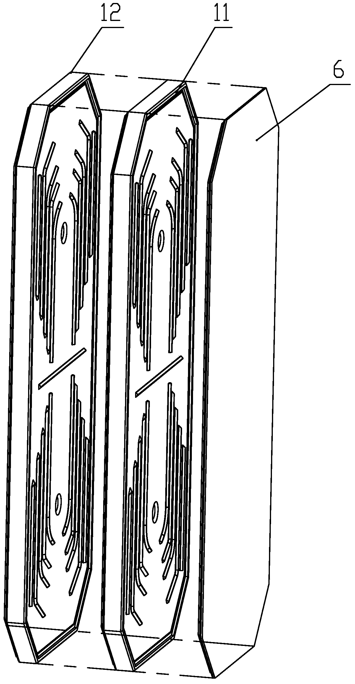
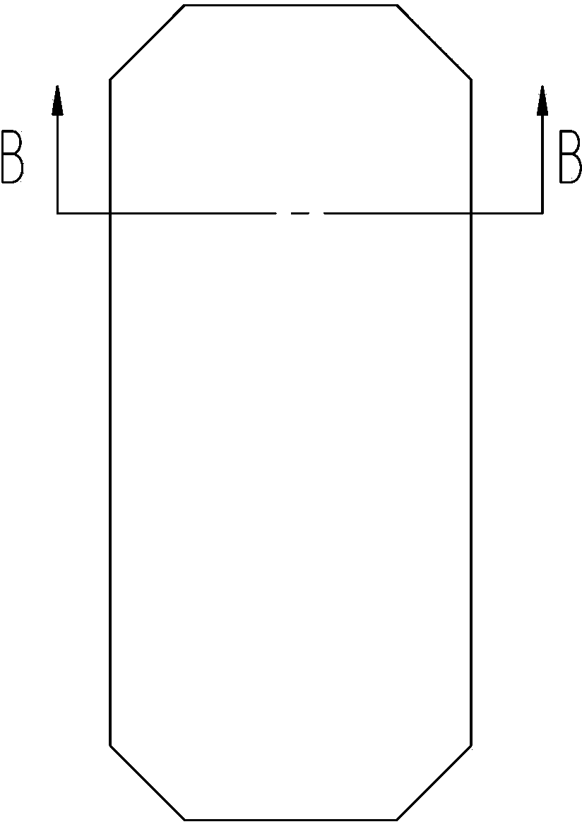
[0038] This embodiment provides a heat exchanger, such as Figure 1 to Figure 6 As shown, the heat exchanger includes two heat exchange plate assemblies filled with heat storage material that are arranged butted against each other, namely a first heat exchange plate assembly 11 and a second heat exchange plate assembly 12 . A first through pipe 2 and a second through pipe 3 are pierced through the two heat exchange plate assemblies, and the first through pipe 2 is arranged higher than the second through pipe 3 . The two first through pipes 2 on the two heat exchange plate assemblies are arranged oppositely, and the two second through pipes 3 are arranged correspondingly.
[0039] Wherein, the heat storage material is a phase change heat storage material, preferably, the phase change heat storage material is a graphite paraffin wax material. Graphite paraffin is a kind of composite material. Graphite is made into a composite graphite paraffin material by absorbing paraffin in ...
Embodiment 2
[0050] This embodiment provides a heat exchanger whose structure is basically the same as that of Embodiment 1, such as Figure 9 As shown, it includes two heat exchange plate assemblies that are arranged butted against each other and filled with heat storage material inside, namely a first heat exchange plate assembly 11 and a second heat exchange plate assembly 12 . A first through pipe 2 and a second through pipe 3 pass through the first heat exchange plate assembly 11 .
[0051] The difference is that only the first through pipe 2 is provided on the second heat exchange plate assembly 12 , which corresponds to the first through pipe 2 on the first heat exchange plate assembly 11 . The first through pipe 2 on the second heat exchange plate assembly 12 is set as the refrigerant inlet, while the refrigerant outlet is set on the end cover 6, which is specifically arranged on the second through pipe 3 of the first heat exchange plate assembly 11. at the location. The working ...
Embodiment 3
[0054] This embodiment provides a heat exchanger, such as Figure 10 and Figure 11 As shown, its structure is basically the same as that of Embodiment 1, including two heat exchange plate assemblies that are filled with heat storage materials, respectively, the first heat exchange plate assembly 11 and the second heat exchange plate assembly 12 . A first through pipe 2 and a second through pipe 3 are pierced through the two heat exchange plate assemblies, and the first through pipe 2 is arranged higher than the second through pipe 3 . The two first through pipes 2 on the two heat exchange plate assemblies are arranged oppositely, and the two second through pipes 3 are arranged correspondingly. The first heat exchange plate assembly 11 and the second heat exchange plate assembly 12 have the same structure, and both include a heat exchange plate body 4 and a cover plate 5, and the heat exchange plate body 4 is provided with an accommodating groove 41 for accommodating heat sto...
PUM
 Abstract
Description
Claims
Application Information
 - R&D
- Intellectual Property
- Life Sciences
- Materials
- Tech Scout
- Unparalleled Data Quality
- Higher Quality Content
- 60% Fewer Hallucinations
Browse by: Latest US Patents, China's latest patents, Technical Efficacy Thesaurus, Application Domain, Technology Topic, Popular Technical Reports.
© 2025 PatSnap. All rights reserved.Legal|Privacy policy|Modern Slavery Act Transparency Statement|Sitemap|About US| Contact US: help@patsnap.com


