U-shaped polymer insulation profile and manufacturing method thereof
A polymer material and profile technology, applied in the field of polymer material profiles, can solve the problem of reducing the deformation force of U-shaped polymer material profiles
- Summary
- Abstract
- Description
- Claims
- Application Information
AI Technical Summary
Problems solved by technology
Method used
Image
Examples
Embodiment 1
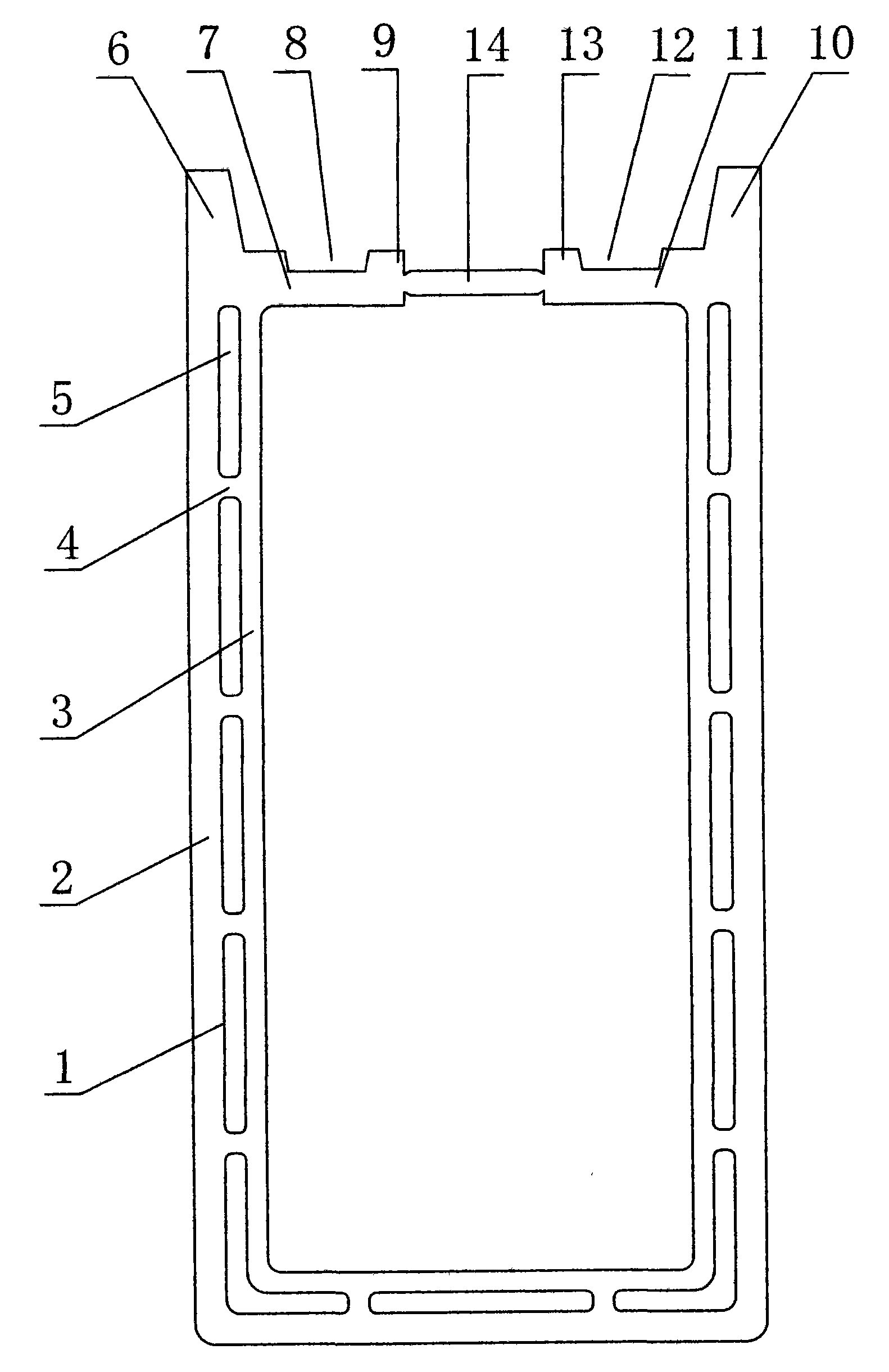
[0035] The structure diagram of the inner and outer double-layer U-shaped polymer material profiles with anti-deformation ties is as follows figure 1 As shown, among them: 1 is the inner and outer double-layer U-shaped polymer material profile, 2 is the outer wall of the U-shaped polymer material profile, 3 is the inner wall of the U-shaped polymer material profile, 4 is the tie bar, 5 is the air cavity, and 6 is the left side Vertical trapezoidal plate, 7 is the left horizontal plate, 8 is the left trapezoidal positioning groove, 9 is the left positioning block, 10 is the right vertical trapezoidal plate, 11 is the right horizontal plate, 12 is the right trapezoidal positioning groove, 13 is the right positioning Block platform, 14 is anti-deformation tie bars.
Embodiment 2
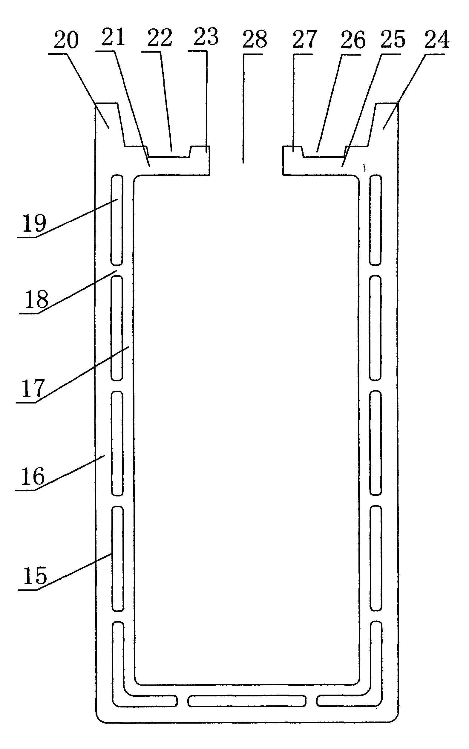
[0037] The structure diagram of U-shaped polymer material profile is as follows figure 2 As shown, among them: 15 is the inner and outer double-layer U-shaped polymer material profile, 16 is the outer wall of the U-shaped polymer material profile, 17 is the inner wall of the U-shaped polymer material profile, 18 is the tie bar, 19 is the air cavity, and 20 is the left Vertical trapezoidal plate, 21 is the left horizontal plate, 22 is the left trapezoidal positioning groove, 23 is the left positioning block, 24 is the right vertical trapezoidal plate, 25 is the right horizontal plate, 26 is the right trapezoidal positioning groove, 27 is the right positioning Block platform, 28 is an opening.
Embodiment 3
[0039] The structure diagram of the PVC inner foam co-extruded U-shaped polymer material profile with anti-deformation ties is as follows image 3 As shown, wherein: 29 is an internal foaming co-extrusion U-shaped polymer material profile, 30 is the outer wall of an internal foaming co-extrusion U-shaped polymer material profile, 31 is an inner foam layer, 32 is a left vertical trapezoidal plate, and 33 is a Left horizontal plate, 34 is the left trapezoidal positioning groove, 35 is the left positioning block, 36 is the right vertical trapezoidal plate, 37 is the right horizontal plate, 38 is the right trapezoidal positioning groove, 39 is the right positioning block, 40 is the anti Deformed stretch.
PUM
 Abstract
Description
Claims
Application Information
 - R&D Engineer
- R&D Manager
- IP Professional
- Industry Leading Data Capabilities
- Powerful AI technology
- Patent DNA Extraction
Browse by: Latest US Patents, China's latest patents, Technical Efficacy Thesaurus, Application Domain, Technology Topic, Popular Technical Reports.
© 2024 PatSnap. All rights reserved.Legal|Privacy policy|Modern Slavery Act Transparency Statement|Sitemap|About US| Contact US: help@patsnap.com


