Large-capacity defrosting valve
A large-capacity, valve body technology, applied in the direction of lift valve, valve detail, multi-way valve, etc., can solve the problem of reducing the heating efficiency of air conditioners, and achieve the effect of improving heating efficiency, small impact and good stability
- Summary
- Abstract
- Description
- Claims
- Application Information
AI Technical Summary
Problems solved by technology
Method used
Image
Examples
Embodiment approach
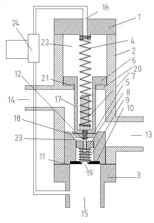
[0021] Figure 7 It is a structural schematic diagram of the open state of the third embodiment of the present invention (the connecting rod and the valve core are integrated);
[0022] Figure 8 It is a structural schematic diagram of the closed state of the third embodiment of the present invention (the connecting rod and the valve core are integrated);
[0023] Figure 9 It is a schematic structural diagram of the open state of the fourth embodiment of the present invention (no septum);
[0024] Figure 10 It is a schematic structural diagram of the closed state of the fourth embodiment of the present invention (no septum);
[0025] Figure 11 It is a schematic structural diagram of the open state of the fifth embodiment of the present invention (the second channel 14 is placed on top);
[0026] Figure 12 It is a schematic structural diagram of the closed state of the fifth embodiment of the present invention (the second channel 14 is placed on top);
[0027] Fig...
Embodiment 1
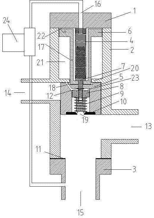
[0031] Example 1: A large-capacity defrost valve (see figure 1 , figure 2 , image 3 , Figure 4 ), which includes a valve body 2, the upper end of the valve body 2 is connected to the upper end cover 1, the valve body 2 is provided with a piston 6, the piston 6 is connected with the valve core 5 through the connecting rod 7, and is locked by the locking pad 12. The upper end of the connecting rod 7 is connected with the extension spring 4, and the upper end of the extension spring 4 is connected with the lower end of the upper end cover 1. The lower end of the spool 5 is provided with a small bonnet 10, the inside of the spool 5 is provided with a small spool 8, the lower part of the small spool 8 is covered with a small spring 9, the small spool 8 is lifted by the small spring 9, and the lower end of the small spring 9 Link to the small valve cover 10. The lower end of the valve body 2 is connected to the lower end cover 3, a gasket 11 is provided between the valve bod...
Embodiment 2
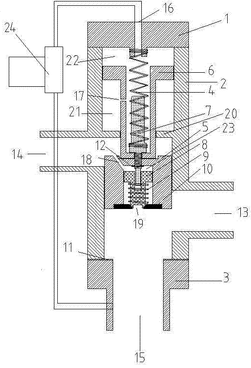
[0039] Embodiment 2: A large-capacity defrosting valve (see Figure 5 and Figure 6), its structure and principle are basically the same as Embodiment 1, the difference is that the fifth channel 17 and the small valve assembly are omitted, that is, there is no small The spool 8, the small spring 9, the small valve cover 10, the sixth passage 18 and the seventh passage 19 have only one stage of pressure relief.
[0040] When the high-temperature and high-pressure fluid in the second channel 14 arrives, the gas flow passes through the gap between the piston 6 and the partition 20, and throttles to the buffer chamber 21, and the piston 6 is forced upward to prevent the valve core 5 from moving downward. After the gap between the piston 6 and the valve body 2 is throttled to the power chamber 22, the upper surface of the piston 6 is stressed, pushing the piston 6 to move downward, but it is slowly lowered by the resistance of the buffer chamber 21. When the valve core 5 moves to the ...
PUM
 Abstract
Description
Claims
Application Information
 - Generate Ideas
- Intellectual Property
- Life Sciences
- Materials
- Tech Scout
- Unparalleled Data Quality
- Higher Quality Content
- 60% Fewer Hallucinations
Browse by: Latest US Patents, China's latest patents, Technical Efficacy Thesaurus, Application Domain, Technology Topic, Popular Technical Reports.
© 2025 PatSnap. All rights reserved.Legal|Privacy policy|Modern Slavery Act Transparency Statement|Sitemap|About US| Contact US: help@patsnap.com


