Waste gas recycling buffer system of vulcanizing tank

A waste gas recovery and buffer system technology, applied in chemical instruments and methods, separation of dispersed particles, use of liquid separation agents, etc., can solve problems such as accidents, small amounts of solids, and blocked pipelines, and achieve reasonable design, simple structure, Solve the effect of easy clogging

Inactive Publication Date: 2014-12-24
天津天元亨橡胶制品厂
View PDF0 Cites 1 Cited by
  • Summary
  • Abstract
  • Description
  • Claims
  • Application Information

AI Technical Summary

Problems solved by technology

However, there is a problem that a small amount of solids or impurities brought in by some gases will be produced during the waste gas treatment process. If they are not treated in time, they will block the pipeline, cause backflow, and even cause accidents.

Method used


Image

  • Waste gas recycling buffer system of vulcanizing tank

Examples


Embodiment Construction

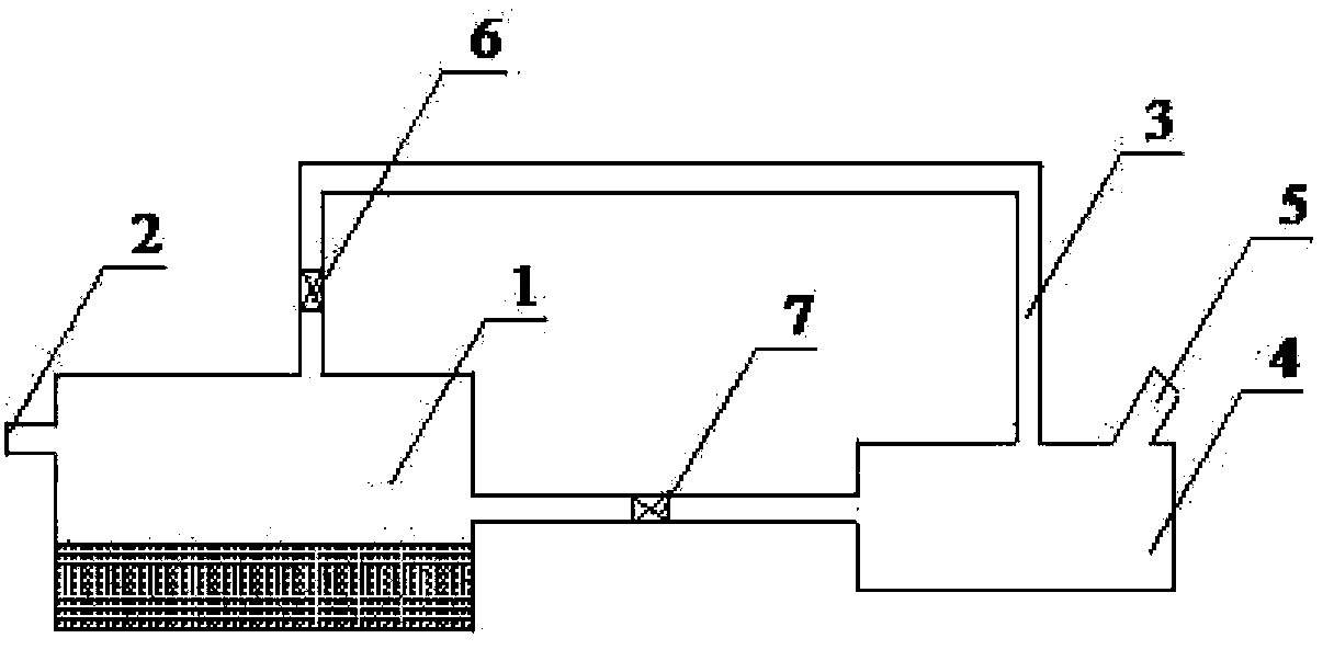
[0012] A vulcanization tank waste gas recovery buffer system of the present invention comprises a waste gas recovery tank 1, the waste gas recovery tank 1 is provided with an inlet pipe 2 and an air outlet pipe 3, and there is a certain amount of absorption liquid in the waste gas recovery tank 1, and the waste gas recovery tank 1 passes through the pipe Road links to each other with glove box 4, and buffer pipe 5 communicates with the outside world on the glove box 4, and air outlet pipe 3 communicates with glove box 4.

[0013] An exhaust valve 6 is provided between the outlet pipe 3 and the exhaust gas recovery tank 1 , and a safety overflow valve 7 is provided between the glove box 4 and the exhaust gas recovery tank 1 .

[0014] The exhaust gas recovery process mainly absorbs and treats the exhaust gas through the absorption liquid in the exhaust gas recovery tank 1. According to common sense, the absorption liquid in the exhaust gas recovery tank 1 also needs to be update...


PUM


Abstract

The invention provides a waste gas recycling buffer system of a vulcanizing tank. The waste gas recycling buffer system comprises a waste gas recycling tank, a gas inlet pipe and a gas outlet pipe are arranged on the waste gas recycling tank, and a defined amount of absorbing liquid is arranged in the waste gas recycling tank. The waste gas recycling buffer system is characterized in that the waste gas recycling tank is connected with a sundry box by virtue of a pipeline, a buffer pipe is arranged on the sundry box and is communicated with the outside, and the gas outlet pipe is communicated with the sundry box. An exhaust valve is arranged between the gas outlet pipe and the waste gas recycling tank, and a safety overflow valve is arranged between the sundry box and the waste gas recycling tank. The waste gas recycling buffer system has the advantages and the positive effects of being simple in structure and reasonable in design, being capable of overcoming the difficulty that an existing waste gas recycling tank is likely to block, being capable of collecting waste generated in a waste gas recycling process and being simple and convenient.

Description

technical field [0001] The invention relates to a waste gas recovery device, in particular to a vulcanization tank waste gas recovery buffer system Background technique [0002] In the rubber production process, a large amount of waste gas will be generated during the vulcanization process, which needs to be treated. Generally, the method of passing it into the waste gas recovery tank and using liquid is used for recovery. During this process, harmful waste gas is absorbed by the liquid in the waste gas recovery tank , the treated gas is discharged into the atmosphere through the pipeline. However, there is a problem that a small amount of solids or impurities brought in by some gases will be produced during the waste gas treatment process. If they are not treated in time, they will block the pipeline, cause backflow, and even cause accidents. Contents of the invention [0003] The purpose of the present invention is to provide a vulcanization tank waste gas recovery buff...

Claims


Application Information

Patent Timeline
Patent Type & Authority Applications(China)
IPC IPC(8): B01D53/18B01D47/02
Inventor 张伟杰郭金春林树喜
Owner 天津天元亨橡胶制品厂
Why Eureka
Try Eureka