Racemization system and racemization method of aero-optical remote sensor

An optical remote sensor and aeronautical technology, which is applied in the field of aeronautical optical remote sensors, can solve the problems of reducing the control accuracy of the K mirror speed loop, damage to the structural components, and reducing the control accuracy, and achieves strong adaptability to the environment, strong anti-interference ability, and stability. The effect of improved accuracy

Active Publication Date: 2016-09-21
BEIJING RES INST OF SPATIAL MECHANICAL & ELECTRICAL TECH
View PDF4 Cites 0 Cited by
  • Summary
  • Abstract
  • Description
  • Claims
  • Application Information

AI Technical Summary

Problems solved by technology

For detection components, the current K-mirror of the 45° scanning mirror imaging system often uses an encoder or gyro detection method. For the field of aerial reconnaissance, the vibration shock of the carrier aircraft and the drastic changes in high and low temperatures have a greater impact on the encoder, followed by the gyro Affected by its own accuracy and zero drift stability, reduce the control accuracy of the K mirror speed loop
For the actuator, the K mirror of the current 45° scanning mirror imaging system is often driven indirectly by a servo motor with a reducer or directly driven by a DC torque motor. The former uses a reducer to introduce transmission errors to reduce the control accuracy, and the latter torque motor can ° Rotation and derotation itself The rotation angle is in the range of ±15°. Due to improper control or operation, the motor often hits the structural components and causes damage to the structural components.
[0003] At the same time, for the swing-sweep imaging system, the feedback value of the K-mirror tracking scanning angle of the current 45° scanning mirror imaging system does not consider the speed-to-height ratio change of the carrier, so the real-time performance is poor, and there is a certain delay in the elimination of the image rotation.

Method used


Image

  • Racemization system and racemization method of aero-optical remote sensor
  • Racemization system and racemization method of aero-optical remote sensor
  • Racemization system and racemization method of aero-optical remote sensor

Examples


Embodiment Construction

[0021] Specific embodiments of the present invention will be further described in detail below in conjunction with the accompanying drawings.

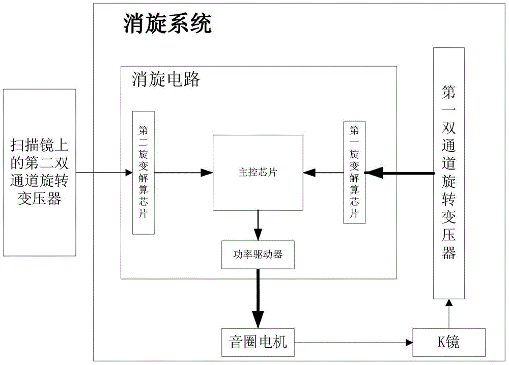
[0022] Such as figure 1 As shown, the present invention proposes a derotation system of an aeronautical optical remote sensor, including a K mirror, a derotation circuit, a dual-channel resolver and a voice coil motor with limited rotation angle. The derotation circuit includes the first resolver chip H2S44, the second resolver chip H2S44, the main control chip DSP2812 and the power driver L6205; the dual-channel resolver is installed on the K mirror to measure the rotation angle of the K mirror, and the The measured rotation angle is output to the first resolver chip H2S44 in the derotation circuit; the second resolver chip H2S44 in the derotation circuit receives the scanning angle of the scanning mirror; the voice coil motor with limited rotation angle and derotation The power driver L6205 of the circuit is connected; the main cont...


PUM


Abstract

The invention discloses a derotation system and a derotation method of an aeronautical optical remote sensor, which mainly solves the problem of image rotation in the imaging process of a 45° scanning mirror system, resulting in blurred images and difficulties in subsequent image processing. The invention realizes the derotation of the imaging of the 45° scanning mirror, is applicable to various spectral bands of light, greatly reduces the weight and space of the equipment, and improves the quick response performance, control precision and service life of the system. The invention has the characteristics of fast response speed, strong tracking performance, high stability, compact structure and long service life, etc., and has been successfully used in an aviation optical remote sensor model.

Description

technical field [0001] The invention relates to a derotation system and a derotation method of an aeronautical optical remote sensor, belonging to the field of aeronautical optical remote sensors. Background technique [0002] In the field of aerial reconnaissance, it is often necessary to be applicable to a variety of spectral bands of light, and at the same time it is required to obtain wide-angle, high-resolution panoramic images within a limited time. In the field of aerial optical remote sensing, 45° scanning mirror imaging is often used to meet the above requirements. Because the 45°rotation scanning will produce image rotation, it will bring difficulties to the later image processing. The Dove prism can effectively eliminate the image rotation caused by 45° rotation, but it cannot meet the requirements of the mid- and far-infrared bands. The K mirror can make up for the defects of the Dove prism, not only can eliminate the image rotation, but also is suitable for mul...

Claims


Application Information

Patent Timeline
Patent Type & Authority Patents(China)
IPC IPC(8): G02B7/00G02B26/10
Inventor 王哲林招荣李福东佟杰吴春楠宋立国安超贾晓梅马杨李林鹏张倩李冰
Owner BEIJING RES INST OF SPATIAL MECHANICAL & ELECTRICAL TECH
Why Eureka
Try Eureka