
Mesh belt type veneer drier

A drying machine and mesh belt technology, which is applied in the direction of drying solid materials, promoting the preliminary treatment of solid material drying, drying, etc., and can solve the problems of uneven drying and unsmooth feeding.

Inactive Publication Date: 2014-12-17
凭祥长隆人造板有限公司
View PDF5 Cites 3 Cited by
  • Summary
  • Abstract
  • Description
  • Claims
  • Application Information

AI Technical Summary

Problems solved by technology

[0008] In order to overcome the defects of uneven drying and unsmooth feeding of the existing mesh belt type veneer dryer due to the uneven surface of the veneer, the present invention provides a mesh belt type veneer dryer, the veneer dryer After leveling the uneven veneer, it is placed at the feeding port of the conveyor belt, so that the veneer and the mesh belt can be closely bonded, so that the veneer can smoothly enter the drying room for drying, and the drying is uniform

Method used

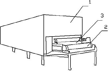

Image

  • Mesh belt type veneer drier
  • Mesh belt type veneer drier
  • Mesh belt type veneer drier

Examples


Embodiment 1

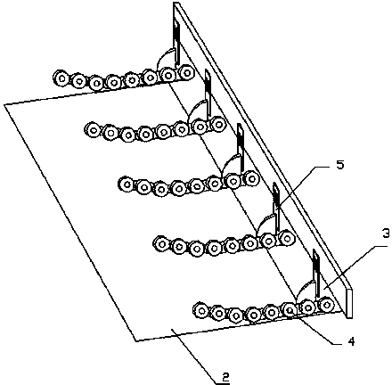
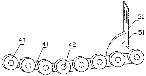
[0033] The present embodiment comprises mesh belt 2, sprocket wheel and drying chamber 1, and mesh belt 2 is driven by sprocket wheel, and drying chamber 1 is provided with feed inlet 3, and mesh belt 2 enters into drying chamber 1 from feed inlet 3, in drying A veneer leveling device is added at the feed port 3 of the chamber 1, and the veneer leveling device includes a plurality of leveling units 4 and a plurality of connecting pieces 5, one leveling unit 4 is connected to a connecting piece 5, and the leveling unit 4 passes through the connecting piece 5 Connected to the feed port 3 of the drying chamber 1, the flattening unit 4 includes a plurality of pinch rollers 40 and a pinch roller connector, and the plurality of pinch rollers 40 are connected together through the pinch roller connector.

[0034] The leveling units 4 are installed parallel to each other at equal intervals, and the installation height of the pressure rollers 40 of the leveling units 4 decreases graduall...

Embodiment 2

[0038] The present embodiment comprises mesh belt 2, sprocket wheel and drying chamber 1, and mesh belt 2 is driven by sprocket wheel, and drying chamber 1 is provided with feed inlet 3, and mesh belt 2 enters into drying chamber 1 from feed inlet 3, in drying A veneer leveling device is added at the feed port 3 of the chamber 1, and the veneer leveling device includes a plurality of leveling units 4 and a plurality of connecting pieces 5, one leveling unit 4 is connected to a connecting piece 5, and the leveling unit 4 passes through the connecting piece 5 Connected to the feed port 3 of the drying chamber 1, the flattening unit 4 includes a plurality of pinch rollers 40 and a pinch roller connector, and the plurality of pinch rollers 40 are connected together through the pinch roller connector.

[0039] The leveling units 4 are installed parallel to each other at equal intervals, and the installation height of the pressure rollers 40 of the leveling units 4 decreases graduall...


PUM


Abstract

The invention discloses a mesh belt type veneer drier. The mesh belt type veneer drier comprises a mesh belt, a chain wheel and a drying room, wherein the mesh belt is driven by the chain wheel; a feeding hole is formed in the drying room; the mesh belt enters the drying room from the feeding hole; a veneer smoothening device is mounted at the feeding hole; the veneer smoothening device comprises a plurality of smoothening units and a plurality of connecting pieces, one smoothening unit is connected to one connecting piece, the smoothening units are connected to the feeding hole of the drying room through the connecting pieces, each smoothening unit comprises a plurality of pressing wheels and a plurality of pressing wheel connecting pieces, and the pressing wheels are connected together through the pressing wheel connecting pieces. Non-smooth veneers are tightly attached to the mesh belt at the feeding hole of a conveyor belt after the non-sooth veneers are smoothened, so that the veneers can smoothly enter the drying room for drying, and the veneers are uniformly dried.

Description

technical field [0001] The invention relates to a device for plywood production, in particular to a mesh belt type veneer dryer for drying veneers that have been rotary cut. Background technique [0002] Plywood is a wood-based panel made of veneers with different grain directions. The veneer textures of its adjacent layers usually form a 90° angle with each other. The structure is mostly odd-numbered layers, and in special cases, it is also made into even-numbered layers such as 4 layers and 6 layers. Because plywood has the characteristics of small deformation, large format, convenient construction, not easy to warp, and high tensile strength of transverse grain, it is widely used in furniture, carriages, shipbuilding, military industry, packaging and other industrial sectors. [0003] The production process of ordinary plywood is: log - cutting - heat treatment - peeling - centering - rotary cutting - drying (or shearing) - shearing (or drying) - repairing - gluing - B...

Claims


Application Information

Patent Timeline
IPC IPC(8): F26B1/00B27D5/00
Inventor 马华军
Owner 凭祥长隆人造板有限公司
Learn More