Mechanical punching pile

A technology of mechanical drilling and hole piles, applied in sheet pile walls, drilling equipment, earthwork drilling and other directions, can solve the problems of soil collapse, labor and material consumption, etc., achieve good vibration damping effect, convenient drilling, reduce The effect of frequency

Inactive Publication Date: 2014-12-17
浙江冶民园林工程有限公司
View PDF6 Cites 3 Cited by
  • Summary
  • Abstract
  • Description
  • Claims
  • Application Information

AI Technical Summary

Problems solved by technology

Ordinary perforated piles can only be simply drilled. There are certain defects in filling the holes, protecting the mechanical parts and the stability of the whole machine. If there is no better way to incorporate it into the design, after the piling is completed Finally, the piling equipment such as the drill bit will be evacuated from the hole. If the soil is loose, it will cause the soil to collapse and bury the hole, resulting in wasted work and rework, which consumes both manpower and material resources, and increases the piling cost.

Method used


Image

  • Mechanical punching pile

Examples


Embodiment Construction

[0014] The present invention is described in further detail now in conjunction with accompanying drawing. These drawings are all simplified schematic diagrams, which only illustrate the basic structure of the present invention in a schematic manner, so they only show the configurations related to the present invention.

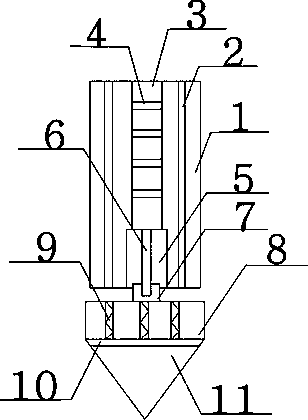
[0015] Such as figure 1 The preferred embodiment of the mechanical perforated pile shown in the present invention comprises a hole pile cylinder 1, and a cement pipeline 2 is vertically arranged in the hole pile cylinder 1, and there are two cement pipelines 2, and between the two cement pipelines 2 Rib plate 3, a layer of wear-resistant material 4 is arranged horizontally on the rib plate 3, a hydraulic cylinder 5 is provided at the bottom of the rib plate 3, and the mechanical connection between the rib plate 3 and the hydraulic cylinder 5 is installed in the hydraulic cylinder 5. The shaft 6, the top of the hydraulic shaft 6 passes through the hydraulic cy...


PUM


Abstract

The invention discloses a mechanical punching pile. The mechanical punching pile comprises a hole pile barrel, wherein two cement pipelines are vertically arranged in the hole pile barrel; a reinforced rib plate is arranged between the two cement pipelines; a wear-resistant material layer is transversely arranged on the reinforced rib plate; the bottom of the reinforced rib plate is provided with a hydraulic cylinder; the reinforced rib plate is mechanically connected with the hydraulic cylinder; a hydraulic shaft is arranged in the hydraulic cylinder; the top of the hydraulic shaft passes through the hydraulic cylinder, and is mechanically connected with the reinforced rib plate; the bottom of the hydraulic shaft extends into a protection groove; the bottom of the protection groove is positioned on a motor, and is connected with the motor through a mechanical shaft; the motor is movably connected with the hydraulic shaft through a connecting rod; an anti-shock device is arranged in the motor. The mechanical punching pile is convenient for punching, and has a good damping function; when a drill bit is not extracted from a hole, cement slurry is introduced through the cement pipelines to fill the hole; moreover, a certain wear resisting effect can be achieved, and the component replacing frequency is lowered; furthermore, the motor is arranged on the lower part of the hole pile barrel, so that the motor can be protected to a certain degree.

Description

technical field [0001] The invention relates to a perforated pile, in particular to a mechanical perforated pile. Background technique [0002] There are many pile foundation engineering construction techniques in construction engineering, and the pile machinery products corresponding to various pile foundation construction techniques are also of various types, with strong specificity, and the manufacturing cost and sales price are also very different. Ordinary perforated piles can only be simply drilled. There are certain defects in filling the holes, protecting the mechanical parts and the stability of the whole machine. If there is no better way to incorporate it into the design, after the piling is completed Finally, the drill bit and other piling equipment will be evacuated out of the hole. If the soil is loose, the soil will collapse and the hole will be buried, resulting in wasted work and rework, which consumes manpower and material resources and increases the cost o...

Claims


Application Information

Patent Timeline
Patent Type & Authority Applications(China)
IPC IPC(8): E02D7/00E21B12/00
Inventor 龚素华
Owner 浙江冶民园林工程有限公司
Why Eureka
Try Eureka